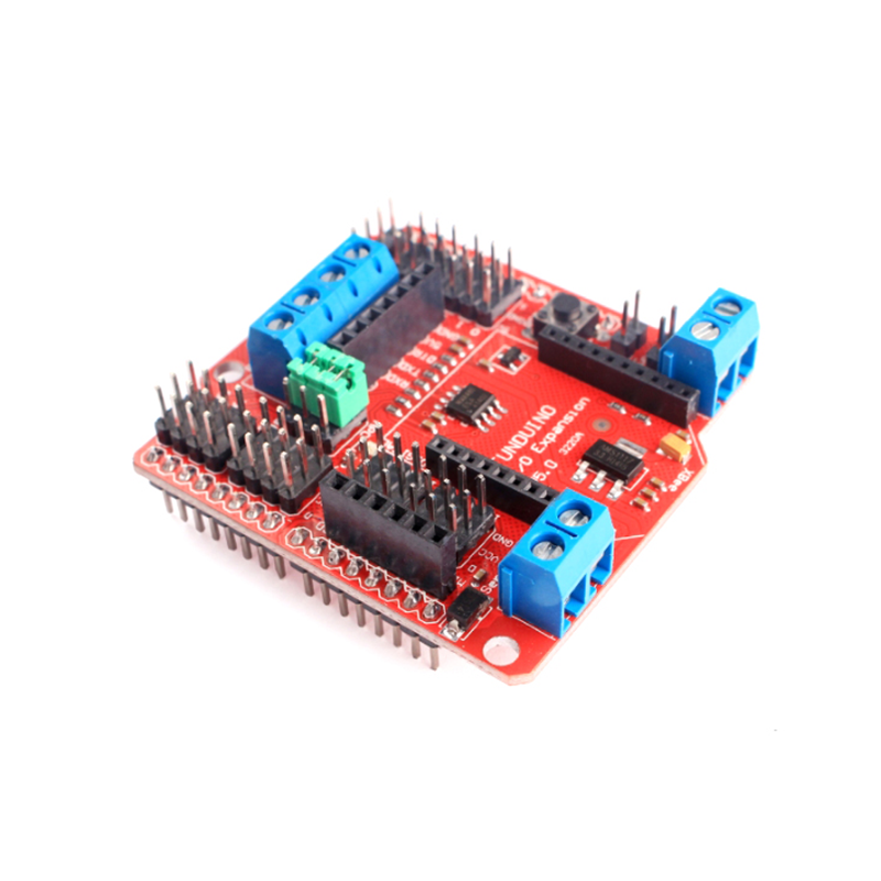


Description:
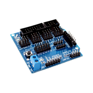
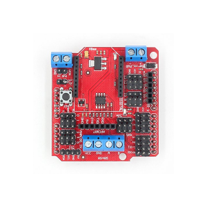
- Our IO expansion board is evolving, this latest V5 IO expansion shield is now supporting Xbee. It combines our popular Xbee shield
- with IO expansion shield(V4). It even supports SD card which provides the ultimate
- functional expansion for Arduino so far. As its predecessor, it supports RS485, APC220,
- Bluetooth communication, servo control.
Specification:
- Support RS485
- Support Xbee (Xbee pro)
- Support Bluetooth
- Support APC220
- Support SD card read/write
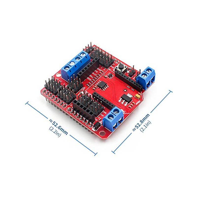
- 1. extension of 14 digital IO ports (12 servo interface) and power;
- 2.6 analog IO ports and power;
- 3.1 digital external power port terminal;
- 4. Digital-port external power supply and an onboard power supply automatic switching;
- 5.1 External power input terminal and an input pin;
- 6.RS485 interface;
- 7. reset button;
- 8.xbee/Bluetooh Bee Bluetooth wireless data transmission interface;
- 9.APC220/Bluetooh V3 Bluetooth wireless data transmission interface;
- 10.IIC/I2C/TWI interface;
- 11.3.3V output port;
- 12.SD card module interface;
RS485:
- It uses an SP485CN chip to handle comms.
- The screw terminals (assuming that the three jumpers are set to ‘485’) marked ‘A’ and ‘B’ go directly to the IC ‘A’ and ‘B’ pins (6 & 7 respectively).
- The screw terminal marked VCC goes to the IC VCC pin (8), and also to the board’s +5V line
- The screw terminal marked GND goes to the IC GND pin (5), and also to the board’s GND line
- The chip’s DI (Data Input?) pin (4) is connected to for Arduino’s Digital Pin 1 (TX).
- The chip’s RO (Data Output?) pin (1) is connected to for Arduino’s Digital Pin 0 (RX), with a resistor pull-up to the +5V rail.
- The chip’s DE (output enable) pin (3) is connected (via a resistor) to for Arduino’s Digital Pin 2 – this is active high.
- This DE pin is also connected to the chip’s RE bar (receiver enable) pin (2) and therefore controlled by for Arduino’s Digital pin 2 too – this is active low.
- Digital Pin 2 = Rx/Tx ‘Enable’; High to Transmit, Low to Receive
- So, to transmit data from for Arduino Digital Pin 1 you need to take Digital pin 2 high, and to receive data to for Arduino Digital Pin 0 you need to take Digital pin 2 low.
- It combines our popular Xbee shield
Note:
The color (red/black) shipped is random, please make a note if you have any requirements!