Description
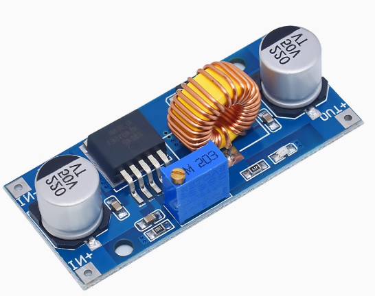
The XL4015 5A DC-DC Adjustable Buck Converter Module is a high-performance, high-power step-down switching regulator designed for applications requiring efficient voltage reduction. Whether you need to power 5V microcontrollers from a 12V battery, drive 12V LED strips from a 24V supply, or create a custom adjustable power supply, this module delivers reliable, efficient performance.
At the heart of this module is the XL4015 chip from XLSEMI – a 180KHz fixed frequency PWM buck converter that integrates a high-current 5A power MOSFET . This advanced design achieves conversion efficiencies of up to 96%, significantly outperforming older LM2596-based modules (which typically max out at 1.8A-2A continuous output) .
Key Technical Advantages over LM2596:
Comprehensive Protection Features :
-
Built-in thermal shutdown – Automatically shuts down when overheated
-
Current limiting – Prevents damage from overload conditions
-
Output short protection – Reduces switching frequency from 180KHz to 48KHz during shorts
-
Over-temperature protection – Auto-restart when temperature normalizes
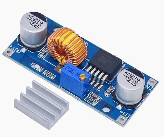
The module includes an adjustable multi-turn potentiometer for fine-tuning output voltage from 1.25V to 36V . A power indicator LED confirms when the module is active, and a heatsink is included for improved thermal management at higher currents.
Wide Application Range:
-
Battery-powered devices: Convert 12V/24V battery banks to 5V for USB charging or Arduino projects
-
LED lighting: Drive 12V LED strips from 24V industrial supplies
-
DIY power supplies: Create custom adjustable bench power supplies
-
Industrial equipment: Step down 24V PLC rails to 5V or 12V for sensors
-
Automotive systems: Convert 12V-24V vehicle electrical systems to stable 5V for dashcams or mobile devices
-
Solar power systems: Regulate higher solar panel voltages to battery charging levels
Important Operating Note: This module is a step-down (buck) converter only. The input voltage must always be higher than the desired output voltage for proper regulation. It cannot step up voltage.
Whether you are an electronics hobbyist, an IoT developer, or an industrial engineer, the XL4015 5A Buck Converter Module provides a powerful, efficient, and reliable solution for all your voltage step-down needs.
Key Features
-
5A High Output Current – Integrated 5A power MOSFET delivers up to 5A peak (4.5A recommended continuous with heatsink)
-
Wide Input Voltage Range – Accepts DC 4V to 38V input, compatible with 12V, 24V, and 36V power systems
-
Adjustable Output Voltage – Output can be set from 1.25V to 36V via onboard multi-turn potentiometer
-
High Conversion Efficiency – Up to 96% efficiency minimizes power loss and heat generation
-
75W Maximum Power – Capable of delivering up to 75W output power (with adequate cooling)
-
180KHz Switching Frequency – Fixed-frequency PWM operation for predictable performance
-
Comprehensive Protection – Built-in thermal shutdown, over-current limiting, and output short protection
-
Low Dropout Voltage – Only 0.3V dropout ensures efficient operation even with small input-output differentials
-
Power Indicator LED – Visual confirmation of module activity
-
Heatsink Included – Pre-installed heatsink for improved thermal management at higher currents
Technical Parameters
Usage Guide
How It Works
The XL4015 is a step-down (buck) switching regulator. It works by rapidly switching a power transistor on and off at 180KHz, storing energy in an inductor during the ON time and releasing it to the output during the OFF time. The output voltage is regulated by adjusting the duty cycle based on feedback from a resistor divider network .
This switching design is far more efficient than linear regulators, especially when there is a large difference between input and output voltage or when delivering high current .
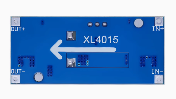
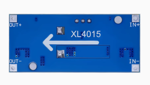
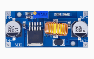
Pinout Description
The module features clearly labeled solder pads and terminals:
Note: Input and output grounds are common (connected together on the board).
Wiring Instructions
Step 1 – Connect Input Power
-
Connect the positive (+) wire of your DC power source to the V-IN pad marked “+”
-
Connect the negative (-) wire of your power source to the V-IN pad marked “-“
-
Observe polarity carefully – reverse polarity will damage the module
Step 2 – Connect Load
Step 3 – Power On and Adjust Output Voltage
Critical Adjustment Note – Multi-Turn Potentiometer
This is the most important point for new users. The module uses a multi-turn potentiometer (typically 25-30 turns from end to end) . If you turn the screw and see no voltage change, you have likely reached the end of the adjustment range and need to turn in the opposite direction.
If the output voltage remains at the input voltage, the potentiometer is at its maximum setting. Turn it counter-clockwise many turns until the voltage starts to decrease.
Current and Thermal Management
While the XL4015 chip is rated for 5A, practical continuous output current depends on cooling :
Important Current Relationship: As a step-down converter, the input current will be lower than the output current:
Input Current = Output Current × (Output Voltage ÷ Input Voltage) ÷ Efficiency
Example: 5V @ 4A output (20W) from a 24V input draws only approximately 0.9A-1A input current.
Heat Management Tips:
-
The included heatsink is pre-installed and should not be removed
-
For continuous loads above 3A, ensure adequate airflow around the module
-
For loads approaching 4.5A continuous, consider adding a fan or larger heatsink
-
The module includes thermal shutdown protection, but good thermal design is still essential
Important Operating Restrictions
Voltage Limitation (Critical):
This module is a step-down (buck) converter only. The input voltage must always be higher than the output voltage for proper regulation. If the input voltage drops below the output voltage, the module cannot boost, and the output will approximately follow the input .
Minimum Dropout:
The module requires approximately 0.3V to 1V of headroom – input voltage should be at least 0.3V higher than the desired output voltage .
Reverse Polarity Warning:
This module does NOT have reverse polarity protection . Double-check your V-IN+ and V-IN- connections before applying power. Connecting backwards will instantly destroy the module.
Short Circuit Behavior:
When the output is shorted, the module reduces its switching frequency from 180KHz to 48KHz and limits current . However, this is not a full short-circuit protection feature. Avoid prolonged short circuits.
Example Applications
Installation Tips
-
Polarity Check: Always double-check input polarity before applying power
-
Initial Setup: Adjust output voltage with no load connected first
-
Keep Wires Short: Long wires add resistance and voltage drop
-
Capacitor Addition: For noise-sensitive applications, add additional 220µF-470µF capacitor at output
-
Heatsink: The included heatsink is pre-installed – do not remove it
-
Start with Low Load: When first testing, use a low-current load to verify voltage setting before connecting sensitive equipment
Q: What is the difference between XL4015 and LM2596?
The XL4015 is a superior alternative to the older LM2596 :
For any application requiring more than 2A output current, the XL4015 is the better choice.
Q: Why is my output voltage not changing when I turn the potentiometer?
The module uses a multi-turn potentiometer (25-30 full turns from end to end) . If you reach the end of its range, turning further will have no effect. Try turning the screw counter-clockwise many turns until the voltage starts to decrease. If voltage remains at input voltage, the potentiometer is at its maximum – keep turning counter-clockwise.
Q: What is the maximum continuous current I can draw?
With the included heatsink and adequate airflow :
-
2.5A – 3.5A: Safe for continuous operation
-
4A – 4.5A: Requires additional cooling (fan or larger heatsink)
-
5A: Peak/short duration only
The 5A rating is the chip’s switch current limit, not the continuous output rating
Q: Why is my module getting very hot?
Heat is normal in any high-power DC-DC converter. The XL4015 runs hot at high currents due to:
Solutions:
-
Ensure the heatsink is properly attached and has good airflow
-
For loads above 3A, add a small fan or upgrade the heatsink
-
If too hot to touch, reduce the load or improve cooling
Q: Can I use this module for both home and business applications?
Home users: Raspberry Pi power supplies , 12V LED strip drivers from 24V sources, DIY adjustable bench power supplies, battery charging, USB device power from car batteries.
Business users: Industrial equipment power supplies, solar system regulation, LED lighting systems, prototype development, 24V to 5V conversion for sensors, automotive electronics.
Q: Does this module have short circuit or reverse polarity protection?
-
Short circuit: The module has built-in current limiting and reduces frequency during shorts, but prolonged shorts should be avoided
-
Reverse polarity: NO – this module does NOT have reverse polarity protection . Always double-check connections before applying power. Adding a high-current diode in series with the input can provide reverse protection.
Q: What is the efficiency of this module?
The XL4015 achieves up to 96% efficiency under optimal conditions (moderate load, small input-output voltage difference) . Efficiency drops with very large voltage differences or very light/heavy loads. For a 24V to 5V conversion at 4A, expect 85-90% efficiency.
Q: What is the dropout voltage?
The dropout voltage is the minimum difference between input and output for proper regulation. The XL4015 has a very low dropout of only 0.3V . For 5V output, input can be as low as 5.3V and still regulate properly.
Q: What is included in the package?
Q: Can I use this module to charge batteries?
Yes, but with careful voltage setting. Set the output voltage to the battery’s float voltage (e.g., 4.2V for Li-Ion, 12.6V for 3S LiPo). However, this module does not have constant-current charging control – it will attempt to deliver full current. For proper battery charging, use a dedicated CC-CV charger module