XL6009 Adjustable DC-DC Boost Converter Module (4.5-32V to 5-35V) – High-Efficiency Step-Up Voltage Regulator with Digital Voltmeter, Superior to LM2577 Normal version

SKU: FA2102-0
Input Voltage Range

DC 4.5V – 32V (min 4.5V for voltmeter operation)

Output Voltage Range

DC 5V – 35V (adjustable)

Maximum Output Current

4A (peak) / 2.5A (recommended continuous)

Conversion Efficiency

Up to 94%

Switching Frequency

400 kHz

Output Ripple

< 50mV (typical)

Load Regulation

±0.5%

Module Dimensions

43 × 21 × 14 mm

Operating Temperature

-40°C to +85°C

Description

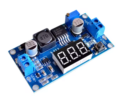
The XL6009 Adjustable DC-DC Boost Converter Module with Digital Voltmeter is a high-performance, feature-rich step-up switching regulator designed to efficiently elevate lower DC voltages to higher, adjustable output levels. Featuring a built-in LED digital voltmeter, this module allows you to monitor both input and output voltages in real-time, making it an indispensable tool for any electronics workbench.

At the heart of this module is the XL6009E1 chip, a second-generation high-frequency switching regulator that integrates a high-current 4A MOSFET switch. This advanced design allows the module to deliver superior performance compared to older LM2577-based modules, with higher efficiency (up to 94%), higher switching frequency (400kHz), and more compact overall dimensions .

Built-in Digital Voltmeter: The integrated LED display shows voltage readings with 0.1V accuracy . A small tactile button allows you to toggle the display between monitoring the input voltage (IN) and output voltage (OUT), with dedicated LED indicators showing which voltage is currently displayed . The voltmeter can also be turned off to save power in battery-operated applications by pressing and holding the button .

Superior to LM2577: The XL6009 represents a significant upgrade over the traditional LM2577. With a 400kHz switching frequency (vs 50kHz), it requires smaller filter capacitors and produces lower output ripple (typically 30-50mV vs 80-120mV) . Higher efficiency (up to 94% vs 75-85%) means less heat generation and better performance in compact designs .

Key Applications:

  • Automotive Voltage Regulation: Stabilizes vehicle electrical systems where voltage can fluctuate between 5V and 32V, maintaining a steady output

  • Solar and Battery Systems: Converts variable battery voltages (3.7V Li-Ion to 5V USB, 7.4V to 12V) for powering devices

  • LED Lighting: Drives 12V or 24V LED strips from 5V USB power banks

  • Portable Electronics: Powers Arduino, ESP32, and other microcontrollers from battery sources

  • DIY Power Supplies: Provides adjustable voltage for prototyping and testing

Important Operating Note: This module is a step-up (boost) converter only. The output voltage must be set higher than the input voltage for proper regulation. If the input exceeds the set output, the module cannot step down, and the output will approximately follow the input, potentially damaging your load .

Whether you are an electronics hobbyist, an IoT developer, or an industrial engineer, the XL6009 Boost Converter Module with Digital Voltmeter provides a powerful, efficient, and user-friendly solution for all your voltage boosting needs.

Key Features

  • Built-in Digital Voltmeter – 0.1V resolution LED display toggles between input and output voltage monitoring with dedicated IN/OUT indicators

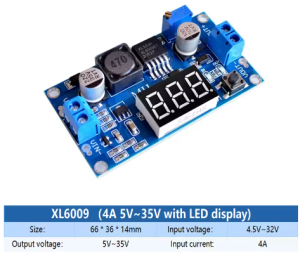
  • Wide Input Voltage Range – Accepts DC 4.5V to 32V input, compatible with USB (5V), Li-Ion batteries (3.7V), and car electrical systems

  • Wide Adjustable Output – Output can be set from 5V up to 35V (some versions up to 52V) via onboard multi-turn potentiometer

  • 4A Peak Output Current – Integrated 4A MOSFET switch delivers up to 4A peak (2A-3A continuous recommended with proper cooling)

  • High Conversion Efficiency – Up to 94% efficiency minimizes power loss and heat generation, outperforming LM2577 modules

  • 400kHz High Switching Frequency – Enables smaller filter capacitors, lower output ripple (30-50mV), and compact module design

  • Voltmeter Power-Saving Mode – Long press the button to turn off the display, reducing power consumption in battery applications

  • Screw Terminal Connections – Easy, solderless wiring for input and output connections

  • Excellent Regulation – ±0.5% load regulation and ±0.5% voltage regulation ensure stable output under varying conditions

  • Wide Operating Temperature – -40°C to +85°C for reliable operation in automotive, industrial, and outdoor environments

Technical Parameters

Parameter Value
Input Voltage Range DC 4.5V – 32V (min 4.5V for voltmeter operation)
Output Voltage Range DC 5V – 35V (adjustable)
Maximum Output Current 4A (peak) / 2.5A (recommended continuous)
Conversion Efficiency Up to 94%
Switching Frequency 400 kHz
Output Ripple < 50mV (typical)
Load Regulation ±0.5%
Module Dimensions 43 × 21 × 14 mm
Operating Temperature -40°C to +85°C

Usage Guide

Product Overview and Voltmeter Operation

The XL6009 module features an integrated LED digital voltmeter that can monitor either the input voltage (from your power source) or the output voltage (supplied to your load) . This feature eliminates the need for a separate multimeter when setting up or monitoring your system.

Voltmeter Controls:

  • Short press the tactile button to toggle between input (IN) and output (OUT) voltage display

  • LED indicators show which voltage is currently being displayed (IN LED or OUT LED)

  • Long press (1-4 seconds) to turn off the voltmeter display (power-saving mode)

  • Short press again to turn the voltmeter back on

Voltmeter Accuracy: The display shows voltage readings with approximately 0.1V accuracy . For precise adjustments, always verify with a separate multimeter.

Note: The voltmeter requires a minimum input voltage of 4.5V to operate. Below this voltage, the display may not function .

Pinout and Connection Description

The module features two sets of screw terminal blocks for easy, solderless wiring:

Terminal Label Function
Left Side (Input) IN+ Input Positive – Connect to your DC power source positive terminal
Left Side (Input) IN- Input Negative – Connect to your DC power source negative terminal (ground)
Right Side (Output) OUT+ Output Positive – Connect to your load’s positive terminal
Right Side (Output) OUT- Output Negative – Connect to your load’s negative terminal (ground)

Important: Input and output grounds are common (connected together on the board).

Wiring Instructions

Step 1 – Connect Input Power

  • Connect the positive (+) wire of your DC power source (battery, power supply, solar panel, etc.) to the IN+ terminal

  • Connect the negative (-) wire of your power source to the IN- terminal

Step 2 – Connect Load

  • Connect the positive (+) wire of your load (device being powered) to the OUT+ terminal

  • Connect the negative (-) wire of your load to the OUT- terminal

Step 3 – Power On and Verify

  • Apply power to the input

  • The voltmeter should illuminate, showing either input or output voltage

  • Use the button to verify both readings are as expected

Adjusting the Output Voltage

⚠️ CRITICAL: The “Endless Turn” Issue

This is the most common point of confusion for new users. The potentiometer often ships at its maximum resistance position. If you turn the screw and see no voltage change, you need to turn it counter-clockwise for up to 15 full rotations before the voltage begins to increase . Keep turning while watching the voltmeter or your multimeter until the voltage starts to rise. The potentiometer is multi-turn, so you won’t damage it by continuing to turn.

Proper Adjustment Procedure:

  1. Power the module using your input source (4.5V-32V DC)

  2. Set voltmeter to output mode (OUT LED lit)

  3. Use a small screwdriver to turn the blue potentiometer:

    • Turn counter-clockwise (left) to INCREASE output voltage

    • Turn clockwise (right) to DECREASE output voltage

  4. Monitor the voltmeter while adjusting

  5. For precise settings, verify with a separate multimeter

Pro Tip: It is recommended to adjust the output voltage before connecting your load. Adjusting the potentiometer while the module is under load may cause voltage spikes that could damage sensitive equipment .

Understanding the Voltmeter Display

The built-in voltmeter provides real-time monitoring of your system:

Display Mode What It Shows When To Use
IN Mode (IN LED lit) Input voltage from your power source Verify your power source is providing adequate voltage
OUT Mode (OUT LED lit) Output voltage to your load Set and monitor the boosted output voltage

Using the Voltmeter for Troubleshooting:

  • If the voltmeter shows significantly lower input voltage than expected, check your power source and connections

  • If the output voltage drops under load, your load may be exceeding the module’s current capability

  • If the voltmeter does not turn on, verify input voltage is at least 4.5V

Current Limitations and Thermal Management

While the XL6009 chip is rated for 4A peak, practical limitations apply based on cooling:

Condition Recommended Max Current
Without heatsink (continuous) 1.5A – 2A
With heatsink (continuous) 2A – 3A
Peak (short duration) 4A

High-Temperature Environments: At ambient temperatures above 40°C (e.g., inside a car engine bay or industrial enclosure), limit continuous current to 1.5A or add a heatsink to the XL6009 chip .

Important Current Relationship: Boost converters draw more input current than output current due to power conservation. The relationship is:

Power In × Efficiency = Power Out or VIN × IIN × Efficiency = VOUT × IOUT

Example: To get 1A at 12V output (12W) from a 5V input, the input current must be approximately 2.5A-3A (accounting for efficiency losses). Ensure your input power source can supply sufficient current.

Heat Management Tips:

  • Add a heatsink to the XL6009 chip for continuous loads above 1.5A

  • Ensure adequate airflow around the module

  • Consider using a higher input voltage to reduce the voltage conversion ratio and associated heat

  • The module has built-in over-temperature protection but good thermal design is still recommended

Important Operating Restrictions

Voltage Limitation (Critical):
This module is a step-up (boost) converter only. It CANNOT step down voltage. The output voltage must always be set higher than the input voltage for proper regulation. If the input voltage exceeds the set output voltage, the module will not regulate down, and the output will approximately follow the input voltage (minus a small diode drop), potentially delivering high voltage to your low-voltage load and destroying it .

Minimum Input Voltage for Voltmeter:

  • The boost converter itself can operate with inputs as low as 3V

  • However, the built-in voltmeter requires a minimum of 4.5V to function

  • If your input is below 4.5V, the voltmeter will not display, but the module may still boost (check with an external multimeter)

Reverse Polarity Warning:
This module does NOT have reverse polarity protection. Double-check your IN+ and IN- connections before applying power. Connecting backwards will instantly destroy the module .

Short Circuit Protection:
Most basic XL6009 modules do not include dedicated short circuit protection. The chip has over-current limiting, but this is not a full protection feature. Adding a small fuse on the input line is good safety practice.

Example Applications

Use Case Input Source Typical Output Voltmeter Use
USB Power Bank to 12V LED Strip 5V USB power bank 12V Monitor output to verify 12V setting
Li-Ion Battery to 5V Arduino 1x 18650 (3.7V-4.2V) 5V Monitor input to check battery level
Car Voltage Stabilizer 12V-14.5V vehicle system 12V Monitor both input and output
Battery Pack to Laptop Charger 12V battery 19V Monitor output to verify correct charging voltage
Solar Panel to Device Variable solar (6V-24V) 12V Monitor input to track solar availability

Installation Tips

  • Polarity Check: Always double-check input polarity before applying power

  • Initial Setup: Adjust output voltage with no load connected first

  • Voltmeter Usage: Use the button to check both input and output voltages periodically

  • Keep Wires Short: Long wires add resistance and inductance, reducing efficiency

  • Use a Fuse: Add a fuse (e.g., 3A-5A) on the input line as safety protection

  • Heat Sinking: For loads >1.5A continuous, attach a heatsink to the XL6009 chip

  • Start with Low Load: When first testing, use a low-current load to verify voltage setting before connecting sensitive equipment

Q: Why is my output voltage not changing when I turn the potentiometer screw?

This is the most common issue. The potentiometer typically needs to be turned counter-clockwise for up to 15 full rotations before the voltage begins to change . Keep turning while watching the voltmeter or a multimeter until the voltage starts to rise. The potentiometer is multi-turn, so you won’t damage it by continuing to turn.

Q: How do I use the built-in voltmeter?
  • Short press the button to toggle between input (IN) and output (OUT) voltage display

  • LED indicators show which voltage is being displayed

  • Long press (1-4 seconds) to turn off the voltmeter (power-saving mode)

  • Short press again to turn it back on

The voltmeter requires a minimum input of 4.5V to operate .

Q: What is the maximum safe current for continuous use?

While the chip is rated for 4A peak, for continuous use:

  • Without heatsink: 1.5A-2A

  • With heatsink: 2A-3A

In high-temperature environments (>40°C), limit to 1.5A or add a heatsink

Q: How does the XL6009 compare to the LM2577?

The XL6009 is a superior modern alternative :

Feature XL6009 LM2577
Switch Current 4A 3A
Switching Frequency 400KHz 50KHz
Efficiency Up to 94% 75-85%
Output Ripple <50mV 80-120mV
Module Size Smaller Larger
Q: Can I use this module to step down voltage (e.g., 12V to 5V)?

No. This module is a boost (step-up) converter only. It cannot step down voltage . If your input is 12V and you need 5V output, you need a buck converter module. If you need both step-up and step-down, use a SEPIC or buck-boost converter.

Q: Why is my voltmeter not turning on?

The built-in voltmeter requires a minimum input voltage of 4.5V to function . If your input voltage is below 4.5V, the voltmeter will not display. However, the boost converter itself may still operate at lower voltages (down to ~3V). Use an external multimeter to verify operation when input is below 4.5V.

Q: Why is my input current so high when boosting?

This is normal physics of boost conversion. Power is conserved: Power In × Efficiency = Power Out. When boosting voltage, input current increases proportionally. Example: 1A at 12V output (12W) from 5V input requires approximately 2.5A-3A input current.

Q: Can I use this module in a car (12V-14.5V electrical system)?

Yes. The XL6009 accepts 4.5V-32V input, making it perfect for automotive use. It can stabilize output to 12V regardless of input fluctuations . However, ensure your load doesn’t exceed current limits and consider adding input protection against voltage spikes.

Q: Does the module have short circuit or reverse polarity protection?

No. Most basic XL6009 modules do not include these protections:

  • Reverse polarity will instantly destroy the module

  • Short circuit may damage the module (the chip has over-current limiting but not full protection)

Always double-check polarity before powering on, and consider adding a fuse on the input.

Q: Can I use this module for both home and business applications?

Home users: Powering 12V LED strips from USB power banks, boosting 3.7V batteries to 5V for Arduino projects, creating custom power supplies, running 12V fans from 5V USB .

Business users: Industrial equipment power supplies, automotive voltage stabilization, solar/wind power conditioning, LED lighting systems, prototype development, remote sensor networks.