Description
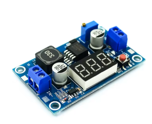
The XL6009 Adjustable DC-DC Boost Converter Module with Digital Voltmeter is a high-performance, feature-rich step-up switching regulator designed to efficiently elevate lower DC voltages to higher, adjustable output levels. Featuring a built-in LED digital voltmeter, this module allows you to monitor both input and output voltages in real-time, making it an indispensable tool for any electronics workbench, from hobbyist projects to industrial applications .
At the heart of this module is the XL6009E1 chip, a second-generation high-frequency switching regulator from XLSEMI that integrates a high-current 4A MOSFET switch . This advanced design delivers superior performance compared to older LM2577-based modules, with higher efficiency, higher switching frequency, and more compact overall dimensions .
Superior to LM2577 – The Key Differences:
The XL6009’s 400kHz switching frequency is a dramatic upgrade over the LM2577’s 52kHz. This higher frequency allows for the use of smaller, lower-cost filter capacitors while achieving lower output ripple and a more compact module design . The higher efficiency (up to 94%) means less power is wasted as heat, improving reliability in compact designs .
Built-in Digital Voltmeter Features:
-
Short press the tactile button to toggle between measuring input voltage (IN) or output voltage (OUT)
-
LED indicators show which voltage is currently being displayed
-
Long press (1-4 seconds) to turn off the voltmeter display (power-saving mode for battery applications)
-
Long press (4+ seconds) to enter calibration mode – adjust voltage measurement offset from -0.5V to +0.5V for high-precision applications
Important Note: The voltmeter requires a minimum input voltage of 4.5V to function. Below this voltage, the display will not illuminate, though the boost converter may still operate at lower voltages .
Wide Operating Range:
-
Input Voltage: 3V – 32V (optimal 5V – 32V)
-
Output Voltage: 5V – 35V (adjustable via onboard potentiometer)
-
Maximum Output Current: 4A peak, 2.5A recommended for continuous use
-
Operating Temperature: -40°C to +85°C
Key Applications:
-
Automotive Voltage Regulation: Stabilizes vehicle electrical systems where voltage can fluctuate between 5V and 32V, maintaining a steady output
-
Battery-Powered Devices: Converts single-cell Li-Ion batteries (3.7V) to 5V, 9V, or 12V for powering microcontrollers and sensors
-
LED Lighting: Drives 12V or 24V LED strips from 5V USB power banks
-
DIY Power Supplies: Provides adjustable voltage for prototyping and testing
-
Solar Power Systems: Converts variable solar panel output to stable voltages for battery charging or equipment power
Important Operating Note: This module is a step-up (boost) converter only. The output voltage must be set higher than the input voltage for proper regulation. If the input exceeds the set output, the module cannot step down, and the output will approximately follow the input, potentially damaging your load .
Whether you are an electronics hobbyist, an IoT developer, or an industrial engineer, the XL6009 Boost Converter Module with Digital Voltmeter provides a powerful, efficient, and user-friendly solution for all your voltage boosting needs.
Key Features
-
Built-in Digital Voltmeter – 0.1V resolution LED display toggles between input and output voltage monitoring with dedicated IN/OUT indicators; includes calibration function for high precision
-
Wide Input Voltage Range – Accepts DC 3V to 32V input (optimal 5V-32V), compatible with USB (5V), Li-Ion batteries (3.7V), and car electrical systems
-
Wide Adjustable Output – Output can be set from 5V up to 35V via onboard multi-turn potentiometer
-
4A Peak Output Current – Integrated 4A MOSFET switch delivers up to 4A peak (2.5A recommended continuous with proper cooling)
-
High Conversion Efficiency – Up to 94% efficiency minimizes power loss and heat generation, significantly outperforming LM2577 modules
-
400kHz High Switching Frequency – Enables smaller filter capacitors, lower output ripple (<50mV), and compact module design
-
Screw Terminal Connections – Easy, solderless wiring for input and output connections
-
Voltmeter Power-Saving Mode – Long press the button to turn off the display, reducing power consumption in battery applications
-
Wide Operating Temperature – -40°C to +85°C for reliable operation in automotive, industrial, and outdoor environments
-
Voltage Calibration Function – Adjust measurement offset (±0.5V) for high-precision applications where 0.1V accuracy is not sufficient
Technical Parameters
Usage Guide
Product Overview and Voltmeter Operation
The XL6009 module features an integrated LED digital voltmeter that can monitor either the input voltage (from your power source) or the output voltage (supplied to your load). This feature eliminates the need for a separate multimeter when setting up or monitoring your system .
Voltmeter Controls:
Voltmeter Calibration:
If your voltmeter readings differ from a trusted reference multimeter:
-
Long press the button for 4+ seconds to enter calibration mode (IN LED will light)
-
Short press to adjust the offset value (-0.5V to +0.5V range)
-
Long press 2+ seconds to save and exit
Important: The voltmeter requires a minimum input voltage of 4.5V to operate. Below this voltage, the display may not function .
Pinout and Connection Description
The module features screw terminal blocks for easy, solderless wiring:
Note: Input and output grounds are common (connected together on the board).
Wiring Instructions
Step 1 – Connect Input Power
-
Connect the positive (+) wire of your DC power source (battery, power supply, solar panel, etc.) to the IN+ terminal
-
Connect the negative (-) wire of your power source to the IN- terminal
Step 2 – Connect Load
Step 3 – Power On and Verify
-
Apply power to the input
-
The voltmeter should illuminate, showing either input or output voltage
-
Use the button to verify both readings are as expected
Adjusting the Output Voltage
⚠️ CRITICAL: The “Endless Turn” Issue
This is the most common point of confusion for new users. The potentiometer often ships at its maximum resistance position. If you turn the screw and see no voltage change, you need to turn it counter-clockwise for 10-15 full rotations before the voltage begins to increase . Keep turning while watching the voltmeter or your multimeter until the voltage starts to rise. The potentiometer is multi-turn, so you won’t damage it by continuing to turn.
Proper Adjustment Procedure:
-
Power the module using your input source (4.5V-32V DC)
-
Set voltmeter to output mode (OUT LED lit)
-
Use a small screwdriver to turn the blue potentiometer:
-
Monitor the voltmeter while adjusting
-
For precise settings, verify with a separate multimeter
Pro Tip: It is recommended to adjust the output voltage before connecting your load. Adjusting the potentiometer while the module is under load may cause voltage spikes that could damage sensitive equipment.
Current Limitations and Thermal Management
While the XL6009 chip is rated for 4A peak, practical limitations apply based on cooling:
Power vs. Current Guidelines:
Important Current Relationship: Boost converters draw more input current than output current due to power conservation. The relationship is:
Power In × Efficiency = Power Out or VIN × IIN × Efficiency = VOUT × IOUT
Example: To get 1A at 12V output (12W) from a 5V input, the input current must be approximately 2.5A-3A (accounting for efficiency losses). Ensure your input power source can supply sufficient current.
Heat Management Tips:
-
Add a heatsink to the XL6009 chip for continuous loads above 1.5A
-
Ensure adequate airflow around the module
-
Consider using a higher input voltage to reduce the voltage conversion ratio and associated heat
-
For applications exceeding 20W, active cooling or a larger heatsink is recommended
Important Operating Restrictions
Voltage Limitation (Critical):
This module is a step-up (boost) converter only. It CANNOT step down voltage . The output voltage must always be set higher than the input voltage for proper regulation. If the input voltage exceeds the set output voltage, the module will not regulate down, and the output will approximately follow the input voltage (minus a small diode drop), potentially delivering high voltage to your low-voltage load and destroying it.
Minimum Input Voltage for Voltmeter:
-
The boost converter itself can operate with inputs as low as 3V
-
However, the built-in voltmeter requires a minimum of 4.5V to function
-
If your input is below 4.5V, the voltmeter will not display, but the module may still boost (check with an external multimeter)
Reverse Polarity Warning:
This module does NOT have reverse polarity protection. Double-check your IN+ and IN- connections before applying power. Connecting backwards will instantly destroy the module.
Short Circuit Protection:
Most basic XL6009 modules do not include dedicated short circuit protection . The chip has over-current limiting, but this is not a full protection feature. Adding a small fuse on the input line is good safety practice.
Understanding the Voltmeter Display
The built-in voltmeter provides real-time monitoring of your system:
Using the Voltmeter for Troubleshooting:
-
If the voltmeter shows significantly lower input voltage than expected, check your power source and connections
-
If the output voltage drops under load, your load may be exceeding the module’s current capability
-
If the voltmeter does not turn on, verify input voltage is at least 4.5V
Example Applications
Installation Tips
-
Polarity Check: Always double-check input polarity before applying power
-
Initial Setup: Adjust output voltage with no load connected first
-
Voltmeter Usage: Use the button to check both input and output voltages periodically
-
Keep Wires Short: Long wires add resistance and inductance, reducing efficiency
-
Use a Fuse: Add a fuse (e.g., 3A-5A) on the input line as safety protection
-
Heat Sinking: For loads >1.5A continuous, attach a heatsink to the XL6009 chip
-
Start with Low Load: When first testing, use a low-current load to verify voltage setting before connecting sensitive equipment
Q: Why is my output voltage not changing when I turn the potentiometer screw?
This is the most common issue. The potentiometer typically needs to be turned counter-clockwise for 10-15 full rotations before the voltage begins to change . Keep turning while watching the voltmeter or a multimeter until the voltage starts to rise. The potentiometer is multi-turn, so you won’t damage it by continuing to turn.
Q: How do I use the built-in voltmeter?
-
Short press the button to toggle between input (IN) and output (OUT) voltage display
-
LED indicators show which voltage is being displayed
-
Long press (1-4 seconds) to turn off the voltmeter (power-saving mode)
-
Short press again to turn it back on
-
Long press (4+ seconds) to enter calibration mode for precision adjustment
The voltmeter requires a minimum input of 4.5V to operate
Q: How do I calibrate the voltmeter for higher precision?
If your voltmeter readings differ from a trusted reference multimeter :
-
Long press the button for 4+ seconds to enter calibration mode (IN LED will light)
-
Short press to adjust the offset value (-0.5V to +0.5V range)
-
Long press 2+ seconds to save and exit
This allows you to achieve better than the default ±0.1V accuracy.
Q: What is the maximum safe current for continuous use?
While the chip is rated for 4A peak, for continuous use :
In high-temperature environments (>40°C), limit to 1.5A or add a heatsink
Q: How does the XL6009 compare to the LM2577?
The XL6009 is a superior modern alternative :
The XL6009 is generally preferred for compact, efficient designs, while LM2577 may be chosen for legacy systems or built-in thermal shutdown protection
Q: Can I use this module to step down voltage (e.g., 12V to 5V)?
No. This module is a boost (step-up) converter only. It cannot step down voltage . If your input is 12V and you need 5V output, you need a buck converter module. If you need both step-up and step-down, use a SEPIC or buck-boost converter.
Q: Why is my voltmeter not turning on?
The built-in voltmeter requires a minimum input voltage of 4.5V to function . If your input voltage is below 4.5V, the voltmeter will not display. However, the boost converter itself may still operate at lower voltages (down to ~3V). Use an external multimeter to verify operation when input is below 4.5V.
Q: Why is my input current so high when boosting?
This is normal physics of boost conversion. Power is conserved: Power In × Efficiency = Power Out. When boosting voltage, input current increases proportionally . Example: 1A at 12V output (12W) from 5V input requires approximately 2.5A-3A input current.
Q: Can I use this module in a car (12V-14.5V electrical system)?
Yes. The XL6009 accepts 4.5V-32V input, making it perfect for automotive use. It can stabilize output to 12V regardless of input fluctuations. However, ensure your load doesn’t exceed current limits and consider adding input protection against voltage spikes.
Q: Does the module have short circuit or reverse polarity protection?
No. Most basic XL6009 modules do not include these protections :
Always double-check polarity before powering on, and consider adding a fuse on the input.

.png)
-300x268.png)
