Product Overview
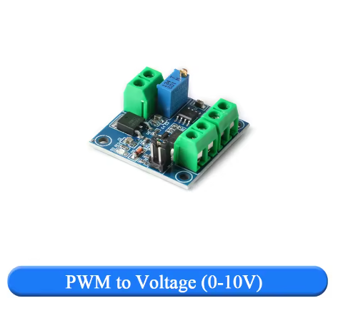
The PWM to Voltage Converter Module is an essential signal interface device designed to bridge the gap between digital microcontrollers and analog industrial equipment. This module converts a Pulse Width Modulation (PWM) signal into a proportional, linear 0-10V DC analog voltage, allowing you to control a vast array of industrial devices using simple digital outputs .
Many modern controllers like Arduino, Raspberry Pi, and various MCUs excel at generating PWM signals but cannot directly output a true 0-10V analog signal. This module solves that problem. By accepting a PWM input (0-100% duty cycle) from your controller, it outputs a clean, adjustable 0-10V voltage that can be used to interface with equipment expecting an analog control signal .
This converter is the perfect tool for integrating low-cost microcontrollers into industrial environments. Its primary applications include:
-
Controlling the speed of industrial motors and pumps via Variable Frequency Drives (VFDs) .
-
Precise dimming of 0-10V dimmable LED drivers and lighting systems .
-
Interfacing with PLC (Programmable Logic Controller) analog input modules .
-
Controlling valve actuators, dampers, and other industrial automation equipment.
-
Providing a stable, adjustable voltage source for testing and laboratory applications.
With its wide input voltage range, selectable logic levels, and onboard calibration, this module provides a professional and reliable solution for translating digital control signals into the analog language of industry .
Key Features
-
Digital to Analog Conversion: Converts a 0%-100% duty cycle PWM digital signal into a linear 0-10V DC analog voltage, with a typical allowable error of less than 5% .
-
Wide Power Supply Range: Operates on a DC supply voltage of 12V to 30V, making it easy to power from existing industrial power rails or a separate 24V supply .
-
Dual Input Logic Level Selection: Features a selectable jumper to match the voltage level of your input PWM signal :
-
Onboard Calibration Potentiometer: Includes a precision trimmer potentiometer that allows you to calibrate the module. By inputting a 50% duty cycle signal, you can adjust the pot to achieve a precise 5.00V output, ensuring accuracy in your specific setup .
-
High-Quality Signal Conditioning: Employs embedded MCU technology and an operational amplifier (such as the LM358) for stable and reliable conversion, smoothing the PWM signal into a clean DC voltage .
-
Opto-Isolation (Model Dependent): Many versions of this module include an optocoupler (like the PC817) to provide electrical isolation between the input signal and the output circuit, protecting your sensitive controller from electrical noise .
-
Compact and Easy-to-Mount Design: Its small PCB footprint (approx. 33mm x 33mm) is ideal for mounting in control panels or enclosures without taking up valuable space .
-
Clear Screw Terminal Connections: Features labeled screw terminals for secure and reliable connections to power, input signal, and output voltage.
Technical Specifications
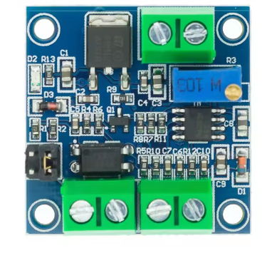
Pinout & Interface Guide
The module features clearly labeled screw terminals for all connections.
Power Supply (Input)
-
VCC / V+ (12-30V): Connect to the positive terminal of an external DC power supply (12V to 30V). This powers the module’s internal circuitry .
-
GND / V- (Ground): Connect to the negative terminal (ground) of the external DC power supply.
PWM Signal (Input)
-
PWM+ / IN+ (Signal Input): Connect to the PWM output pin of your microcontroller (e.g., Arduino) or PLC. The signal level must match the position of the voltage selection jumper .
-
PWM- / GND (Signal Ground): Connect to the ground of your microcontroller or signal source. This is often the same as the power supply ground for non-isolated modules .
Analog Voltage (Output)
-
VOUT / OUT+ (0-10V): This is the converted analog output. Connect this terminal to the 0-10V input of the device you wish to control (e.g., a VFD, LED driver, or PLC analog input) .
-
GND (Output Ground): Connect this to the ground of the receiving device.
Configuration
-
Jumper Cap (5V/24V): This jumper selects the logic level of your input PWM signal. Place it on the pins labeled ‘5V’ for 3.3V/5V signals, and on ’24V’ for 12V-24V signals .
-
Potentiometer: This small screw-adjustable potentiometer is used for calibration. It adjusts the gain of the output circuit .
Usage Guide
Important Pre-Operation Checks
-
Power Supply: Ensure your DC power supply (12-30V) is connected to the VCC and GND terminals with the correct polarity. The module’s power draw is minimal (>100mA) .
-
Signal Level: Crucially, set the jumper to the correct position for your controller. If you are using a 5V Arduino, the jumper must be on the ‘5V’ pins. For a 24V PLC output, it must be on the ’24V’ pins . Setting this incorrectly can result in no output or damage to the module.
-
PWM Frequency: Configure your microcontroller to output a PWM signal with a frequency between 1kHz and 3kHz for optimal performance . Frequencies outside this range may still work but can lead to inaccuracies.
Calibration Procedure
For the most accurate results, calibrate the module to your specific input signal. This is especially recommended the first time you use it .
-
Power Up: Connect the power supply (12-30V) to the module.
-
Send 50% Signal: Program your microcontroller to output a PWM signal with a 50% duty cycle at a frequency between 1-3kHz. The logic level must match your jumper setting (e.g., 5V).
-
Connect Multimeter: Connect a digital multimeter set to measure DC voltage to the VOUT and GND terminals of the module.
-
Adjust Potentiometer: The multimeter should read approximately 5V. Using a small screwdriver, carefully turn the potentiometer on the module until the multimeter reads exactly 5.00V .
-
Calibration Complete: The module is now calibrated. The relationship is now linear: 0% duty cycle = 0V, 50% = 5V, and 100% = 10V.
Wiring Guide (Arduino to VFD)
This example shows how to control a 0-10V input on a Variable Frequency Drive (VFD) using an Arduino.
Example Arduino Code
This code generates a PWM signal on pin 9 with a frequency of approximately 2kHz and sweeps the duty cycle from 0% to 100% and back.
int pwmPin = 9;
int dutyCycle = 0;
void setup() {
TCCR1A = 0b00000011;
TCCR1B = 0b00001001;
ICR1 = 399;
pinMode(pwmPin, OUTPUT);
}
void loop() {
for (dutyCycle = 0; dutyCycle <= 255; dutyCycle++) {
analogWrite(pwmPin, dutyCycle);
delay(15);
}
delay(1000);
for (dutyCycle = 255; dutyCycle >= 0; dutyCycle--) {
analogWrite(pwmPin, dutyCycle);
delay(15);
}
delay(1000);
}
Q: What is the main purpose of this module?
Its main purpose is to act as a translator. It takes a digital PWM signal (0% to 100% duty cycle) from a device like an Arduino and converts it into a smooth, linear 0-10V analog voltage. This allows a low-cost microcontroller to control industrial equipment that uses the 0-10V standard, such as VFDs, valve actuators, and dimmable LED drivers
Q: Why can't I just use a low-pass filter (RC circuit) to convert PWM to voltage?
While a simple RC filter can convert PWM to a DC voltage, its output will sag under even a tiny load and is not precise. This module uses active components (like an op-amp) to buffer the output, providing a clean, stable voltage that can actually drive the input circuits of industrial equipment without losing accuracy
Q: Can this module convert a 0-10V signal back to PWM?
No, this module is designed for one-way conversion from PWM to voltage. For the reverse conversion (voltage to PWM), you would need a different type of module
Q: How do I set the input voltage jumper correctly?
Locate the 3-pin jumper header labeled ‘5V’ and ’24V’. Place the shorting cap on the two pins that match your controller’s logic level .
-
Use the 5V position for 3.3V or 5V signals from Arduinos, Raspberry Pis, or other MCUs.
-
Use the 24V position for 12V or 24V signals from industrial PLCs or sensors.
Q: What PWM frequency should I use?
The module is designed to work best with PWM signals in the 1kHz to 3kHz range . You should configure your microcontroller to output a frequency within this range for the most linear and stable conversion. Frequencies outside this range may still work but could result in reduced accuracy.
Q: Do I have to calibrate the module?
For general use, it may work fine out of the box. However, for applications requiring precise voltage output, calibration is highly recommended. The procedure is simple: input a 50% duty cycle signal and adjust the onboard potentiometer until the output reads exactly 5.00V . This ensures the full 0-10V range is accurate.
Q: What power supply do I need?
You need a DC power supply with a voltage between 12V and 30V. A 24V industrial power supply is a common and excellent choice. The supply must be able to provide at least 100mA of current . This power supply is used to both run the module’s circuitry and to generate the 0-10V output.
Q: My output voltage is not reaching 10V. What could be wrong?
Several factors can cause this:
-
Power Supply Voltage: Your supply voltage (VCC) might be too low. Ensure it is at least 15V, and ideally 24V, to allow the circuit to generate a full 10V output .
-
Calibration: The module may need calibration. Follow the procedure above to adjust the potentiometer.
-
Input Duty Cycle: Ensure your PWM signal is actually reaching 100% duty cycle.
Q: How much current can the 0-10V output provide?
The output is designed as a signal, not a power supply. It can typically provide a maximum of 10mA . This is sufficient to drive the high-impedance inputs of most VFDs and PLCs, but it cannot power a device like a motor or a light bulb.
Q: The module has power, but I get 0V output even with a PWM signal.
Follow this checklist:
-
Check Jumper Setting: Is the jumper set to the correct voltage level (5V/24V) for your input signal? .
-
Check PWM Ground: Is the ground of your PWM signal source connected to the PWM- or GND terminal on the module? .
-
Check Power Ground: Is the power supply ground connected correctly?
-
Check PWM Frequency: Is your PWM frequency within the recommended 1kHz-3kHz range? .
-
Check with Multimeter: Use a multimeter to confirm that a PWM signal is actually present on the input pin.
Q: The output voltage fluctuates or is not stable.
This can be caused by:
-
Electrical Noise: Ensure your PWM signal wires are not running parallel to high-power AC lines. Use shielded cable if necessary.
-
Unstable Power Supply: Check that your main DC power supply (12-30V) is stable and well-regulated.
-
PWM Frequency: The frequency might be too low, causing visible ripple. Try increasing the frequency within the 1-3kHz range