Product Overview
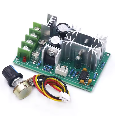
The 20A High-Power PWM DC Motor Speed Controller Module is a robust and versatile speed regulation solution designed for demanding brushed DC motor applications. With broad compatibility across 12V, 24V, 36V, and 48V systems and a continuous current rating of 20A, this controller delivers reliable, efficient, and smooth speed control for a wide range of industrial, automotive, and hobbyist projects .
Utilizing advanced Pulse Width Modulation (PWM) technology, this controller provides stepless speed adjustment from 0% to 100% duty cycle. Unlike simple voltage regulators that reduce torque along with speed, PWM maintains excellent motor torque even at low speeds, ensuring your motor has the power to start and turn loads effectively across its entire speed range .
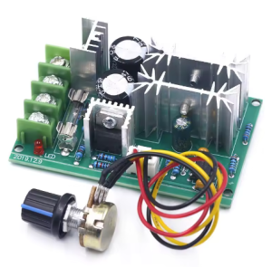
This controller is engineered for versatility and ease of use. It features a high-quality potentiometer with an integrated on/off switch , allowing you to control both power and speed from a single intuitive knob . An onboard LED indicator provides clear visual confirmation when the controller is active, and a replaceable fuse holder offers reliable overload protection .
This controller is the ideal choice for a wide range of demanding applications, including:
-
Industrial Automation: Conveyor systems, production line machinery, packaging equipment
-
Electric Vehicles: E-bikes, scooters, golf carts, mobility scooters (within power limits)
-
Marine Applications: Trolling motors, bilge pumps, livewell pumps
-
Workshop Tools: Bench grinders, drill presses, lathes, band saws, dust collectors
-
Robotics: Large-scale robotic platforms, heavy-duty actuators
-
Renewable Energy: Solar-powered pumps and ventilation systems
-
HVAC: Fan speed control, damper actuators
Key Features
-
Wide Voltage Compatibility: Accepts DC input across 12V, 24V, 36V, and 48V systems, providing exceptional flexibility for a variety of power sources and motor configurations.
-
High Current Capacity: Rated for 20A continuous current with a maximum output power of 1000W (at 48V), delivering substantial power for demanding applications.
-
PWM Technology for Smooth Control: Utilizes high-frequency PWM to provide vibration-free speed adjustment with excellent torque retention even at low speeds, ensuring your motor has the power it needs throughout the speed range.
-
Integrated Potentiometer with On/Off Switch: Features a robust rotary potentiometer that combines on/off control and stepless speed adjustment in a single knob. Turn the knob to power on and increase speed; turn it fully counter-clockwise to switch off.
-
Replaceable Fuse Protection: Includes a user-replaceable fuse holder for reliable overload and short-circuit protection. Easily replace the fuse if a fault occurs—no soldering required.
-
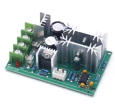
LED Power Indicator: An onboard LED provides clear visual confirmation when power is applied and the controller is active, simplifying troubleshooting and operation monitoring.
-
0%-100% Duty Cycle Adjustment: Allows full range speed control from completely stopped to maximum speed, with linear response to knob rotation.
-
Easy 4-Terminal Wiring: Simple screw terminal connections for power input (V+/V-) and motor output (M+/M-) make installation quick and error-free, with terminals sized for heavy-gauge wire.
-
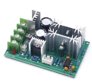
Rugged Construction: Built with industrial-grade components and a robust PCB designed to handle the thermal demands of continuous 20A operation.
Technical Specifications
Pinout & Interface Guide
The controller features clearly labeled screw terminals for all connections.
Power Terminals
-
V+ / VIN+ (Power Input +): Connect the positive terminal of your DC power source (12V-48V) here. Observe correct polarity (+ to +, – to -). The module accepts 12V, 24V, 36V, and 48V systems.
-
V- / VIN- (Power Input -): Connect the negative terminal (ground) of your DC power source here.
Motor Terminals
Note: The motor wires are non-polarized. If the motor runs in the wrong direction, simply swap the two wires at the M+ and M- terminals.
Control Interface
Status Indicators
Fuse Holder
Usage Guide
Important Safety Warnings
-
DC ONLY: This controller is designed strictly for DC circuits. Never connect it to AC mains power (e.g., 110V or 220V AC). Doing so will instantly destroy the controller and poses a serious fire hazard.
-
Polarity Matters: Do not reverse the positive and negative terminals of the DC power supply. This will damage the controller.
-
Motor Type: This controller is for brushed DC motors only. It is NOT compatible with brushless DC motors (BLDC), stepper motors, or AC motors.
-
Current Limits: The controller is rated for 20A continuous current. Prolonged operation at currents exceeding 20A may cause overheating. The 1000W maximum power rating assumes proper voltage matching and adequate cooling.
-
Proper Wiring: Use appropriately sized wire for 20A operation (minimum 14 AWG recommended) to minimize voltage drop and heating.
Wiring Guide
Step-by-Step Operation
-
Mount the Controller: Secure the module in your enclosure using mounting tape or standoffs. Ensure adequate ventilation for high-power operation.
-
Connect the Motor: Connect your brushed DC motor to the M+ and M- terminals. Polarity is not critical for initial testing—if direction is wrong, swap the wires.
-
Connect the Power Supply: Connect your DC power source (12V, 24V, 36V, or 48V) to the V+ and V- terminals. Ensure the power supply is turned OFF or disconnected during wiring.
-
Set Initial Speed: Turn the potentiometer knob fully counter-clockwise to its OFF position.
-
Apply Power: Turn on your DC power source.
-
Adjust Speed: Slowly turn the potentiometer knob clockwise. You will feel a slight click as the switch engages, and the motor will begin to spin. Continue turning clockwise to increase speed.
-
Stop the Motor: Turn the knob fully counter-clockwise until you feel the click. This disconnects power to the motor.
-
Change Direction (if needed): To reverse the motor’s direction, turn off the power, swap the two motor wires at the M+ and M- terminals, and then reapply power.
Q: What types of motors can I use with this controller?
This controller is designed for brushed DC motors only operating at 12V, 24V, 36V, or 48V. It is ideal for motors found in power tools, pumps, fans, conveyors, and small electric vehicles. It is not compatible with brushless DC motors (BLDC), stepper motors, or AC motors.
Q: What is the real-world current and power limit?
The controller is rated for 20A continuous current. The maximum power depends on your input voltage:
-
At 12V: Up to 240W (12V × 20A)
-
At 24V: Up to 480W (24V × 20A)
-
At 36V: Up to 720W (36V × 20A)
-
At 48V: Up to 960W (48V × 20A)
For sustained operation, it is recommended to stay within the 20A continuous rating. Brief surges may exceed this, but prolonged over-current will trip the fuse.
Q: Can I use this controller with a 24V or 48V battery system?
Yes. The controller accepts any DC voltage from 12V to 48V, making it compatible with 12V, 24V, 36V, and 48V battery packs and power supplies. Always ensure your motor is rated for the voltage you apply.
Q: Can I use this controller to change the direction of my motor?
This model provides speed control only. It does not have a built-in direction switch. However, you can easily change the motor’s direction by swapping the two motor wires at the M+ and M- terminals. Always turn the power off before doing this.
Q: What power supply should I use?
Use a DC power source with a voltage between 12V and 48V that matches your motor’s rated voltage. The power source must be capable of delivering at least the current your motor will draw (up to 20A). Examples include:
-
12V, 24V, 36V, or 48V battery packs
-
12V-48V regulated power supplies
-
Industrial DC power systems
Q: The controller gets warm. Is this normal?
Some warmth is normal when switching currents near 20A. The controller is designed to dissipate heat through its components and PCB. However, if it becomes too hot to touch, you may be exceeding the recommended continuous current rating. Ensure adequate ventilation and check that your motor is not drawing excessive current due to mechanical binding or stalling.
Q: What is the PWM frequency?
The controller typically operates at a high-frequency PWM (often between 1kHz and 25kHz depending on the specific variant), which provides smooth motor operation and minimizes audible noise. High-frequency switching also contributes to better torque retention at low speeds.
Q: Does the potentiometer have an off position?
Yes. The potentiometer has an integrated switch. Turning the knob fully counter-clockwise until you feel a click will completely disconnect power to the motor.
Q: The controller doesn't work. The motor doesn't move.
Follow this checklist:
-
Check Knob Position: Ensure the knob is turned clockwise past the initial “click” to turn the power ON.
-
Check Fuse: If the controller recently stopped working, check the replaceable fuse. If the fuse is blown, replace it with one of the same rating (check your specific module for the correct fuse value).
-
Check Power: Verify with a multimeter that you have the correct DC voltage at the V+ and V- terminals (12V-48V).
-
Check Polarity: Ensure your power supply is connected with the correct polarity (+ to V+, – to V-).
-
Check Connections: Ensure all wires are securely fastened in the screw terminals.
-
Test the Motor: Connect your motor directly to the power source (briefly) to ensure it works.
Q: The motor runs at full speed all the time, and the knob doesn't control it.
This indicates that the power MOSFET may have failed “shorted.” This can happen if the controller was overloaded beyond its capacity, experienced a short circuit, or had reverse polarity applied. You will likely need to replace the controller.
Q: The motor runs in the wrong direction.
This is easily fixed. Turn off the power, swap the two motor wires at the M+ and M- terminals, and then reapply power.
Q: The fuse keeps blowing. What's wrong?
Repeated fuse failure indicates an overload condition. Possible causes:
-
Your motor is drawing more than 20A continuously (check motor specifications)
-
Mechanical binding or stall condition causing excessive current draw
-
Short circuit in the motor wiring or motor itself
-
Motor is too powerful for the controller
Solution: Ensure your motor’s continuous current draw is within 20A. Check for mechanical issues. If the problem persists, consider a higher-rated controller for your application.
Q: Can I use this controller to dim LEDs?
While technically possible, this controller is optimized for inductive loads like motors. For LED dimming, a dedicated LED driver is recommended. If you choose to use this controller for LED applications, ensure the LED load does not exceed the voltage and current ratings.
Q: Is there any reverse polarity protection?
This controller does not typically include reverse polarity protection. Always double-check your connections before applying power. Reversing the input polarity can instantly damage the controller.