Product Overview
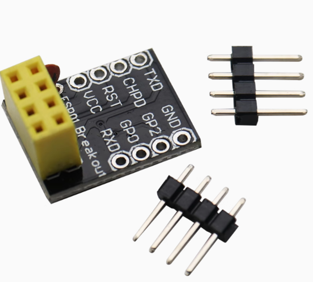
The ESP-01/ESP-01S Breadboard Adapter is an essential accessory for anyone working with the popular ESP8266 WiFi modules. This mini breakout board solves the fundamental challenge of using the ESP-01 module with standard prototyping platforms: its 2×4 pin header does not fit directly into a breadboard. This adapter converts the compact DIP-8 layout into a standard 0.1-inch (2.54mm) pin spacing that is fully compatible with breadboards, perfboards, and standard development boards .
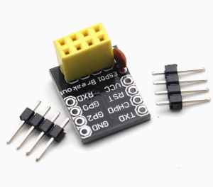
Designed specifically for the ESP-01 and ESP-01S modules, this breakout board provides a stable, reliable platform for prototyping your IoT projects. The module simply plugs into the adapter board, which then provides clear access to all eight pins arranged in a standard 8-pin DIP format . This simple solution eliminates the need for messy jumper wires, reduces connection errors, and provides a professional foundation for your wireless projects .
Whether you are a hobbyist developing smart home devices, an educator teaching IoT concepts, or a professional prototyping wireless sensors, this breadboard adapter is an indispensable tool that saves time, reduces frustration, and ensures reliable connections.
Key Features
-
Direct ESP-01/ESP-01S Compatibility: Designed specifically for the ESP-01 and ESP-01S WiFi modules. The adapter accepts the module’s 2×4 pin header directly, providing a secure mechanical and electrical connection .
-
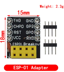
Standard 0.1″ Pin Spacing: Converts the module’s compact DIP-8 layout into standard 2.54mm (0.1-inch) pin spacing, making it fully compatible with standard breadboards, perfboards, and PCB sockets .
-
Plug-and-Play Design: No soldering required for the ESP module connection. Simply plug your ESP-01 into the adapter’s female headers, and then plug the adapter into your breadboard or prototyping platform .
-
Clear Pin Labeling: Each pin is clearly labeled on the adapter board, eliminating guesswork and reducing wiring errors. Pin assignments include VCC, GND, GPIO0, GPIO2, TXD, RXD, RST, and CH_PD/EN .
-
Dual ESP-01/ESP-01S Support: Compatible with both the original ESP-01 (blue PCB) and the updated ESP-01S (black PCB) modules. The adapter accommodates the slight variations between these versions .
-
Compact and Lightweight: The adapter board is sized to minimize footprint on your breadboard, leaving ample space for other components and wiring .
-
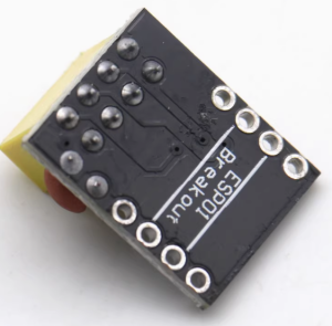
Robust Construction: Built with high-quality FR4 PCB material and precision-milled pin headers for reliable, long-lasting connections .
-
Gold-Plated Pins (Select Models): Some versions feature gold-plated pins for improved corrosion resistance and superior conductivity .
Technical Specifications
Pinout & Interface Guide
Adapter Pin Assignments
The adapter board converts the ESP-01’s 2×4 pin header into a standard 8-pin DIP arrangement. The pin labels are clearly marked on the board:
DIP Package Orientation
When plugged into a breadboard, the adapter provides:
This standard DIP layout makes it easy to connect power, ground, and signal wires using standard breadboard jumper wires.
Usage Guide
Connecting the ESP-01 to the Adapter
-
Align the Module: Position your ESP-01 module with the antenna facing outward from the adapter (or as indicated by the silkscreen on your specific adapter).
-
Insert Gently: Carefully align the module’s 2×4 pin header with the female headers on the adapter. The pins should slide in smoothly—do not force them.
-
Press Firmly: Gently press the module down until it sits flush against the adapter board. Ensure all pins are fully seated.
-
Verify Orientation: Double-check that the module is correctly oriented (pins 1-8 match the adapter’s labeling). Most adapters have a notch or silkscreen indicating proper orientation.
Using on a Breadboard
-
Insert the Adapter: Place the assembled ESP-01 + adapter into your breadboard across the center channel, just like any standard DIP IC.
-
Connect Power: Provide a stable 3.3V DC power supply to the VCC and GND pins. Use the breadboard’s power rails for clean power distribution.
-
Connect Signals: Use standard jumper wires to connect the adapter pins to your other components (sensors, relays, etc.) or to a USB-to-TTL adapter for programming.
-
Add Decoupling Capacitors: For stable operation, add a 10µF to 100µF electrolytic capacitor and a 0.1µF ceramic capacitor between VCC and GND near the adapter.
Programming the ESP-01 on the Adapter
The adapter makes it easy to connect a USB-to-TTL programmer for uploading code:
Enter Programming Mode:
-
Connect GPIO0 to GND (use a jumper wire)
-
Ensure EN/CH_PD is connected to VCC (pull HIGH)
-
Power on or reset the module (RST to GND momentarily)
-
Upload firmware
-
After upload, disconnect GPIO0 from GND and reset
Q: What is the difference between ESP-01 and ESP-01S? Are both compatible?
Yes, both are compatible. The ESP-01 and ESP-01S have the same physical pin layout and will fit into this adapter. The ESP-01S is an optimized version with a slightly different circuit (including a pull-up resistor on the EN pin) but is mechanically identical for mounting purposes.
Q: Do I need to solder anything to use this adapter?
No soldering is required to connect the ESP-01 module to the adapter. The adapter features female headers that accept the module’s pins directly. However, if you want to connect wires to the adapter’s male pins, you may need to solder if using solid-core wire, or you can simply plug it into a breadboard and use jumper wires.
Q: Why can't I just plug the ESP-01 directly into a breadboard?
The ESP-01 uses a 2×4 pin header with 0.1-inch spacing between pins within each row, but 0.2-inch spacing between the two rows . This does not match the standard 0.1-inch grid of a breadboard. The adapter converts this layout to a standard 8-pin DIP configuration that fits perfectly.
Q: Does this adapter work with other ESP modules like ESP-12 or NodeMCU?
No. This adapter is specifically designed for the ESP-01 and ESP-01S modules. Other ESP modules have different pin configurations and will not fit.
Q: Does the adapter provide any voltage regulation?
No. This is a passive breakout board with no active components. It simply routes the pins from the ESP-01 to a breadboard-friendly format. You must provide a stable 3.3V power supply externally .
Q: What power supply should I use with the adapter?
Use a 3.3V DC power supply capable of providing at least 300mA. Options include:
-
3.3V output from an Arduino (check current capability)
-
AMS1117-3.3 or LM1117-3.3 voltage regulator
-
3.3V USB-to-TTL adapter (for programming only, not for sustained operation)
-
3.3V battery pack
Q: Do I need pull-up resistors when using this adapter?
The adapter itself does not add resistors. The ESP-01S has an internal pull-up on EN/CH_PD, but the original ESP-01 may require an external pull-up resistor (typically 4.7kΩ to 12kΩ) on the EN pin for reliable operation . Check your specific module’s requirements.
Q: Can I program the ESP-01 while it's on the adapter?
Yes. The adapter provides easy access to all programming pins. Simply connect a USB-to-TTL adapter to the VCC, GND, TXD, and RXD pins, and pull GPIO0 LOW during boot to enter programming mode.
Q: Why can't I upload code to my ESP-01 when using the adapter?
Common issues:
-
GPIO0 not pulled LOW during power-on (use a jumper wire)
-
Insufficient power supply (USB-to-TTL adapters often cannot provide enough current)
-
Incorrect wiring (TX to RX, RX to TX)
-
EN/CH_PD not connected to VCC (must be HIGH)
-
Loose connection between ESP-01 and adapter (ensure fully seated)
Q: The adapter pins are loose in the breadboard. What should I do?
Over time, breadboard contacts can loosen. If the adapter wobbles:
-
Ensure the adapter is inserted fully and straight
-
Use a breadboard with tighter contacts
-
Consider adding a thin layer of solder to the male pins to increase thickness
-
Use female-to-female jumper wires instead of direct breadboard insertion
Q: How do I reset the ESP-01 when using the adapter?
You can reset the module by:
-
Momentarily connecting the RST pin to GND (using a jumper wire)
-
Cycling power (disconnect and reconnect VCC)
-
Adding a push-button between RST and GND for easy reset access
Q: What can I build with this adapter?
This adapter is the foundation for many ESP-01 projects:
-
Wi-Fi controlled relays (ESP-01 + relay module)
-
Temperature/humidity sensors (ESP-01 + DHT22)
-
Smart switches and home automation
-
IoT data loggers
-
Wireless sensor networks
-
Custom development platforms
Q: Can I use this adapter with a 5V Arduino?
Yes, but with caution. The ESP-01 operates at 3.3V logic and is not 5V tolerant. If connecting to a 5V Arduino:
-
Use a logic level converter for TX/RX lines
-
Do not connect 5V to VCC—use a 3.3V regulator
-
Some 5V signals may work without a converter, but this is not recommended for reliability
Q: Can I use this adapter for permanent installations?
The adapter is designed for prototyping. For permanent installations, consider soldering wires directly to the ESP-01 pins or using a custom PCB. The adapter can be used in permanent projects if secured properly (e.g., with hot glue or mounting tape).