Product Overview
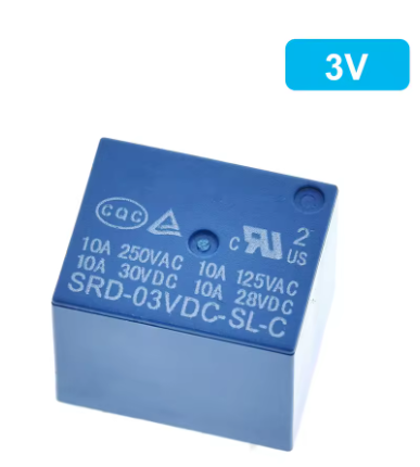
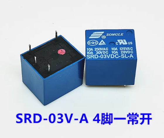
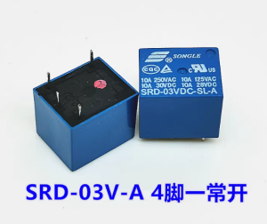
The SRD-03VDC-SL-A is a high-quality, subminiature electromagnetic relay manufactured by Songle (Songle Relay) , one of the most trusted names in the relay industry. This 4-pin, 1 Form A (SPST-NO) relay is designed to switch loads up to 10A at 250V AC or 30V DC, making it an ideal choice for a wide range of applications including home appliances, office equipment, audio systems, and industrial control circuits .
With a 3V DC coil, this relay is perfect for low-voltage control applications where a 3V logic signal is available. The relay features a sealed construction that protects the internal contacts from dust, humidity, and environmental contaminants, ensuring long-term reliability even in demanding conditions . It is recognized by major safety agencies including UL, CUL, and TUV, providing confidence for both hobbyist and commercial applications .
The SRD series relay employs a simple magnetic circuit design that enables high-density PCB mounting while maintaining a compact footprint. Its SPDT (Single Pole Double Throw) configuration provides both Normally Open (NO) and Normally Closed (NC) contact options, allowing flexible wiring for your specific application needs .
Key Features
-
Compact Subminiature Design: Small footprint ideal for high-density PCB mounting applications
-
10A High Switching Capacity: Contacts rated for 10A at 250V AC or 10A at 30V DC, suitable for controlling lights, fans, pumps, and small motors
-
3V DC Coil Voltage: Standard operating voltage of 3V DC with a coil resistance of approximately 25Ω
-
SPST-NO Contact Configuration (1 Form A): Single Pole Single Throw, Normally Open configuration with 4 pins
-
Sealed Construction: Protects internal contacts from dust, moisture, and environmental contaminants
-
Safety Agency Approvals: UL, CUL, and TUV recognized for reliable performance
-
Wide Operating Temperature: Rated for operation from -25°C to +70°C
-
Low Coil Power Consumption: Approximately 0.36W (for high-sensitivity version) ensuring low power draw from your control circuit
Technical Specifications
Pinout & Interface Guide
The SRD-03VDC-SL-A features 4 pins arranged in a standard configuration:
Wiring Diagram
[Coil Connection]          [Switch Contacts]
    +  ----------          COM ---
    |                       |
   [Relay Coil]             NO ---  (Open when coil de-energized)
    |                       |
    -  ----------          (NC pin not present on 4-pin version)
Pin Identification
-
Coil Pins (1 & 2): Non-polarized—they can be connected in either orientation, though observing polarity is recommended for consistent operation
-
Contact Pins (3 & 4): When the coil is de-energized, COM and NO are open. When the coil is energized (3V applied), COM and NO are closed
Usage Guide
Driving the Relay
The SRD-03VDC-SL-A requires approximately 120mA of current to energize the coil (calculated from I = V/R = 3V / 25Ω). This is too much current for most microcontroller pins to source directly.
Recommended Driver Circuit (with NPN Transistor)
    +3V --------[Relay Coil]----+----- +3V (for logic)
                                  |
                                  |/ C
                     Arduino Pin ----|  2N2222 or BC547
                                  |\ E
                                  |
                                GND

                   [Flyback Diode] (1N4148 or 1N4007)
                        +----|<|----+
                        |           |
                  [Relay Coil]       |
                        |           |
                      GND           |
                        +-----------+
Driver Circuit with MOSFET
For lower power consumption and faster switching, a logic-level N-channel MOSFET (such as BS170 or 2N7000) can be used with a gate resistor.
Basic Arduino Control Example
const int relayPin = 7;
void setup() {
pinMode(relayPin, OUTPUT);
digitalWrite(relayPin, LOW);
}
void loop() {
digitalWrite(relayPin, HIGH);
delay(5000);
digitalWrite(relayPin, LOW);
delay(5000);
}
Load Connection Guidelines
-
For AC Loads (e.g., lights, fans):
-
Connect the Live (L) wire to the COM terminal
-
Connect the Load to the NO terminal
-
Connect the Neutral (N) wire directly to the load’s neutral
-
For DC Loads (e.g., motors, solenoids):
-
Connect the positive (+) supply to the COM terminal
-
Connect the load’s positive wire to the NO terminal
-
Connect the load’s negative wire directly to the power supply ground
Important: Flyback Diode
Always use a flyback diode (1N4148, 1N4007, or similar) across the relay coil terminals. When the coil is de-energized, it generates a high-voltage spike that can damage the transistor or microcontroller. The diode should be placed with the cathode (banded end) towards the positive supply and the anode towards the transistor collector.
PCB Layout Considerations
-
Ensure adequate trace width for 10A switching current (recommended ≥ 2mm for 1oz copper)
-
Keep high-current traces away from sensitive signal traces
-
Provide proper clearance between coil and contact traces for safety (≥ 3mm for 250V AC)
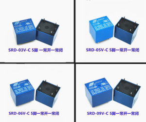
Q: What is the difference between SRD-03VDC-SL-A and SRD-03VDC-SL-C?
The SRD-SL-A is a 4-pin SPST-NO (Single Pole Single Throw, Normally Open) relay with only COM and NO contacts. The SRD-SL-C is a 5-pin SPDT (Single Pole Double Throw) relay with COM, NO, and NC contacts. Choose the A version if you only need to turn a device ON when the relay is activated; choose the C version if you need both NO and NC functions .
Q: What is the maximum load this relay can handle?
The contacts are rated for 10A at 250V AC (resistive) or 10A at 30V DC . For inductive loads like motors or solenoids, it is recommended to derate to 5A–7A to account for startup surges .
Q: Can I use this relay directly with an Arduino or ESP32?
No, not directly. The relay coil draws approximately 120mA at 3V, which exceeds the maximum current rating of most microcontroller pins (typically 20mA–40mA). You must use a transistor driver circuit (NPN transistor or MOSFET) to interface the relay with a microcontroller .
Q: What is the purpose of the flyback diode?
When the relay coil is de-energized, it generates a high-voltage inductive kickback (often >50V) that can destroy the transistor or microcontroller. A flyback diode (1N4148, 1N4007) placed across the coil protects the driver circuit by providing a safe path for this energy to recirculate .
Q: What is the difference between Form A and Form C contacts?
Form A (1 Form A) is SPST-NO (Single Pole Single Throw, Normally Open) —the contacts are open when the relay is de-energized. Form C (1 Form C) is SPDT (Single Pole Double Throw) —provides both NO and NC contacts for more flexible switching .
Q: What is the coil resistance of this relay?
The SRD-03VDC-SL-A has a coil resistance of 25Ω ± 10%. This determines the current draw: I = V / R = 3V / 25Ω = 120mA .
Q: What is the minimum voltage required to activate the relay?
The pick-up (pull-in) voltage is ≤ 75% of nominal voltage, meaning the relay will reliably activate when the coil voltage reaches 2.25V or higher . However, it is recommended to use the full 3V for consistent operation.
Q: What is the drop-out voltage?
The drop-out (release) voltage is ≥ 10% of nominal voltage, so the relay will de-energize when the coil voltage drops below 0.3V .
Q: What is the expected lifespan of this relay?
The relay is rated for 10 million mechanical operations (no load) and 100,000 electrical operations at the rated load. Actual lifespan depends on switching frequency and load type.
Q: Does the relay require a heatsink?
No. The relay is designed for PCB mounting with natural cooling. At 10A continuous load, the contacts may warm slightly, but no additional heatsink is required.
Q: Can I use this relay for 220V AC applications?
Yes. The contacts are rated for 10A at 250V AC, which is suitable for 220V/240V systems. Ensure proper insulation and clearance between coil and contact pins for safety .
Q: The relay clicks but my load doesn't turn on. What's wrong?
This indicates the coil is energizing but the load circuit is incomplete. Check:
-
The load’s wiring (COM to power source, NO to load)
-
The load’s neutral/ground is connected correctly
-
The load itself is functional
-
Contact continuity with a multimeter (should show closed when coil energized)
Q: The relay chatters or buzzes. What causes this?
Chatter usually indicates:
-
Insufficient coil voltage (below 2.25V)
-
Unstable power supply
-
Insufficient driver current
-
Loose connections
-
Contact contamination from switching inductive loads without proper suppression
Q: Can I use this relay in high-vibration environments?
The relay is rated for 10G shock resistance and 10-55Hz vibration at 1.5mm amplitude. For extreme vibration applications, consider using a relay with additional mechanical reinforcement or a solid-state relay (SSR) .
Q: What can I build with the SRD-03VDC-SL-A relay?
Popular applications include:
-
Home automation (lighting, fans, appliances)
-
Industrial equipment control
-
IoT projects with 3V control signals
-
Remote power switching
-
Motor control (with appropriate contact rating)
-
HVAC system control
-
Security systems and alarms
Q: Can I use this relay with a 3.7V lithium battery?
Yes. The relay is rated for 3V nominal but will operate reliably up to 3.9V (120% of nominal). A fully charged lithium battery (4.2V) exceeds the maximum allowable voltage and may shorten the relay’s lifespan. Use a voltage regulator or resistor to limit voltage to ≤ 3.6V.
Q: Is this relay suitable for controlling a pump or motor?
Yes, with derating. For inductive loads like motors, it is recommended to operate at 50–70% of the rated contact current (5A–7A) to account for startup surges. Consider adding a snubber circuit (RC network) across the contacts to suppress arcing .