Description
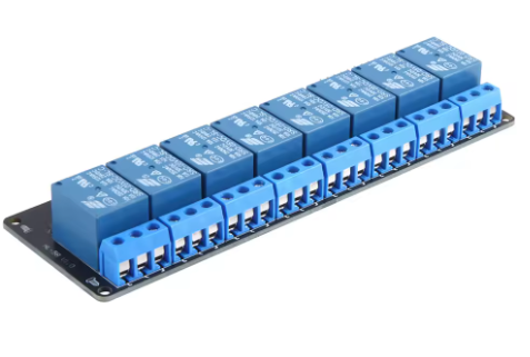
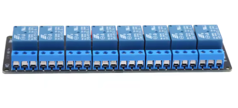
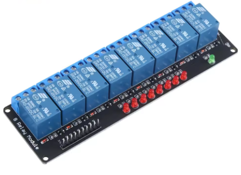
The 5V 8-Channel Relay Module (Non-Optocoupler Version) is a practical and cost-effective control board designed to allow low-voltage circuits (such as Arduino, Raspberry Pi, ESP32, STM32, or other 5V microcontrollers) to independently switch up to eight high-power loads. These include lamps, solenoid valves, motors, pumps, and household appliances.
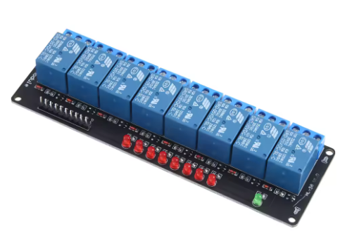
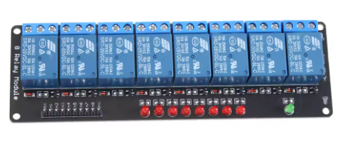
Unlike optocoupler-based versions, this module offers a simplified, direct-drive design using transistor switching. It is ideal for applications where isolation is not critical, and you need a reliable, compact solution for controlling multiple AC or DC devices. Each channel features a visible LED indicator to confirm relay activation status, simplifying debugging and operation.
This module is perfect for DIY home automation, industrial control prototyping, robotic projects, and educational use.
Features
-
8 independent relays with status LEDs
-
Direct 5V TTL logic level control
-
High-current relay contacts (10A per channel)
-
Standard male headers for easy wiring
-
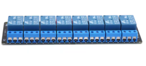
Screw terminals for high-voltage connections
-
Low power consumption design
-
Active HIGH trigger (easy to program)
-
Compact board layout for panel mounting
Technical Parameters
Q: What is the difference between this and the optocoupler version?
This version uses direct transistor drive without optical isolation. It is more affordable and works well for low-noise environments. The optocoupler version offers electrical separation between the microcontroller and the load, which is safer for industrial or noisy environments.
Q: Can I use this with a 3.3V microcontroller like ESP32 or Raspberry Pi Pico?
Yes, but 3.3V logic may be borderline. The module reliably triggers at ≥2.5V. We recommend using a level shifter or testing one channel first. For 3.3V systems, consider adding a transistor buffer.
Q: Why does my relay not turn off after setting the pin to LOW?
Check your wiring – ensure the module’s GND is connected to the microcontroller’s GND. Also, confirm you are not using a pull-up resistor on the control pin.
Q: Can I control AC and DC loads at the same time?
Yes, each relay is independent. You can mix AC and DC loads across different channels as long as you respect the voltage/current limits per relay.
Q: What happens if I power the module with 5V but apply a higher voltage to the relay contacts?
The relay contacts are rated for up to 250V AC or 30V DC. Exceeding this may cause arcing, contact welding, or fire. Always stay within specifications.
Q: How much current does the module draw from the 5V supply?
-
Idle (all relays OFF): ~5–10 mA
-
One relay active: ~70–80 mA
-
All 8 relays active: ~550–650 mA
We recommend a 5V/1A power supply for full load operation.
Q: Is this module suitable for controlling household AC power directly?
Yes, but you must enclose the module in an insulated case and follow local electrical safety codes. Do not touch any terminal while AC power is connected.
Q: Can I use this module for business / industrial automation?
Absolutely. Many small-scale automation projects, greenhouse controls, and smart panel builders use this module. For heavy industrial use with high EMI, we recommend the optocoupler version instead.