Description
The 2A DC-DC Boost Converter Module is a compact and highly efficient power solution designed to elevate lower DC voltages to higher, usable levels. Whether you need to power a 12V LED strip from a 5V USB port, run an Arduino project from a single 3.7V lithium battery, or create a custom power supply for your electronics projects, this tiny module is an essential tool for any workbench.
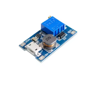
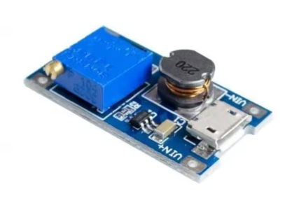
This module accepts a wide input voltage range of 2V to 24V DC and boosts it to an adjustable output voltage from 5V up to 28V DC . The output voltage is easily set using the onboard precision potentiometer, allowing you to dial in common voltages such as 5V, 9V, 12V, 15V, or 24V with a simple screwdriver turn .
A standout feature of this module is the Micro USB interface integrated directly onto the board . This allows you to power the module from common USB sources such as phone chargers, power banks, or computer USB ports without needing to solder wires to the input pads. Simply connect a standard micro USB cable, and you can generate 9V, 12V, or higher voltages from a 5V USB source .
At the heart of this module is the MT2577 (or functionally equivalent MT3608) step-up converter chip. This chip operates at a high 1.2MHz switching frequency, allowing the module to use small, low-profile components while maintaining high efficiency . The module features an internal 4A switch current limit, enabling peak output currents of up to 2A (1A recommended for continuous use without additional cooling) .
How It Works: As a dedicated “Boost” converter, this module only steps voltage up. It works by rapidly switching current through an inductor to build a magnetic field, then releasing that stored energy at a higher voltage. Because the output voltage must always be higher than the input, this module is not suitable for “stepping down” voltage (e.g., converting 12V to 5V).
Important Operating Note: The output voltage must always be greater than the input voltage. If the input voltage exceeds the set output voltage, the module cannot regulate down, and the output will roughly follow the input voltage, which may damage your connected load.
Whether you are a hobbyist powering a portable speaker, an IoT developer needing a 5V rail from a battery, or a professional creating a custom power supply, this MT2577-based boost converter module provides a simple, reliable, and low-cost solution for all your voltage boosting needs.
Key Features
-
Wide Input Voltage Range – Accepts DC 2V to 24V input, compatible with single-cell Li-Ion batteries (3.7V), USB (5V), and various battery packs
-
Adjustable Output Voltage – Output can be set from 5V up to 28V DC via onboard potentiometer (5V/9V/12V/24V typical)
-
Micro USB Input Interface – Integrated micro USB port allows direct powering from phone chargers, power banks, or computer USB ports
-
High Output Current – Delivers up to 2A peak current (1A recommended for continuous use without heatsink)
-
High Conversion Efficiency – Up to 93% efficiency, minimizing power loss and heat generation
-
1.2MHz Switching Frequency – Allows use of small, low-cost external components and reduces output ripple
-
Compact PCB Design – Small footprint (approx. 30-36mm x 17mm) with clearly labeled input/output pads and micro USB port
-
Simple Adjustment – Multi-turn potentiometer allows precise voltage tuning with a screwdriver
-
Onboard Indicator – Power indicator LED shows when module is active
-
Wide Operating Temperature – -40°C to +85°C for reliable operation in various environments
Technical Parameters
Usage Guide
Pinout and Interface Description
The module features multiple connection options:
Wiring Instructions
Method 1 – Using Micro USB Input (Recommended for 5V Sources):
-
Connect a standard micro USB cable to the module’s micro USB port
-
Connect the other end to a 5V USB source (phone charger, power bank, computer USB port, USB hub)
-
The module will power on and the indicator LED will illuminate
-
Connect your load to the VOUT+ and VOUT- pads
Method 2 – Using Solder Pad Input (For 2V-24V Sources):
-
Solder wires to the VIN+ and VIN- pads
-
Connect VIN+ to the positive terminal of your DC power source (battery, power supply, etc.)
-
Connect VIN- to the negative terminal of your DC power source
-
Connect your load to the VOUT+ and VOUT- pads
Adjusting the Output Voltage
⚠️ CRITICAL: The “Endless Turn” Issue
This is the most common point of confusion for new users. The potentiometers on these modules often ship at their maximum resistance position. If you turn the screw clockwise and see no voltage change, you need to turn it counter-clockwise for 10-20 full rotations before the voltage begins to increase. Keep turning while watching your multimeter until the voltage starts to rise.
Proper Adjustment Procedure:
-
Power the module using either the micro USB port or VIN+/VIN- pads
-
Connect a multimeter to the VOUT+ and VOUT- pads to monitor output voltage
-
Use a small screwdriver to turn the blue potentiometer:
-
Adjust slowly and monitor the voltage reading on your multimeter
-
If voltage doesn’t change, continue turning counter-clockwise for many rotations until it begins to rise
Current Limitations and Thermal Management
While the MT2577/MT3608 chip is rated for a peak output of 2A, the practical continuous current is limited by heat generation .
-
Without Heatsink: For reliable continuous operation, it is recommended to keep the output current under 1A
-
High Current (>1A): If you need to draw more than 1A for extended periods:
-
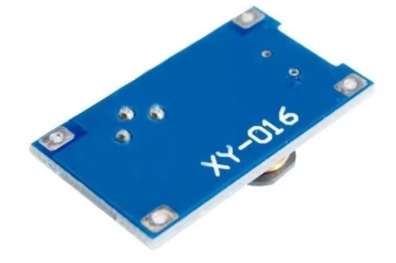
Attach a small heatsink to the MT2577 chip on the back of the board
-
Ensure good airflow around the module
-
Reduce the input-to-output voltage difference when possible
-
Input Current vs. Output Current: Remember that boosting voltage increases current draw from the input source. Example: Drawing 1A at 12V output (12W) from a 5V input will draw over 2.4A from the input source (plus efficiency losses). Ensure your input source can supply sufficient current.
Important Usage Notes
Voltage Limitation:
The output voltage must always be greater than the input voltage. If VIN > VOUT, the module cannot regulate down, and the output will roughly follow the input voltage (minus a small diode drop), potentially delivering high voltage to your low-voltage load and destroying it. Always ensure your desired output voltage is higher than your input voltage .
Reverse Polarity Protection:
This module does NOT have reverse polarity protection. Double-check your VIN+ and VIN- connections before applying power. Connecting backwards will instantly destroy the module.
Micro USB Input Limitations:
When using the micro USB port, the input is limited to standard USB specifications (typically 5V, 500mA-2A depending on the source). For higher input voltages (e.g., 12V battery input), use the solder pad inputs instead.
Typical Applications
Installation Tips
-
Polarity Check: Always double-check input polarity before applying power
-
Input Capacitor: For stable operation, add a 10µF or larger capacitor near the input terminals if your power source has long wires
-
Output Capacitor: A 22µF ceramic capacitor at the output helps reduce voltage ripple for noise-sensitive loads
-
Keep Wires Short: Long wires add resistance and inductance, which can reduce efficiency and cause voltage drops under load
-
Use a Fuse: For critical projects, add a fuse (e.g., 2A) on the input line as a safety precaution against shorts
-
Heat Sinking: For loads approaching 1A continuous, attach a small heatsink to the chip
Q: Why is my output voltage not changing when I turn the potentiometer screw?
This is the most common issue with these modules. The potentiometer typically needs to be turned counter-clockwise for 10-20 full rotations before the voltage starts to change . Keep turning while watching your multimeter until the voltage begins to rise. The potentiometer is multi-turn, so don’t worry about “over-turning” it.
Q: Can I use this module to step down voltage (e.g., 12V to 5V)?
No. This module is a Boost (Step-Up) converter only. It cannot step down voltage . If your input voltage is higher than your set output, the output will roughly equal the input voltage (minus a small diode drop), which may damage your load. For step-down applications, you need a Buck converter module (e.g., LM2596).
Q: What is the maximum safe current for this module?
The chip is rated for 2A peak, but for continuous use without a heatsink, it is recommended to keep the current under 1A to prevent overheating . At 2A, the module will get very hot and may shut down or fail. For higher current requirements, consider using a larger boost converter module.
Q: Can I use this with a 3.7V lithium battery to power a 5V Arduino?
Yes, absolutely. This is one of the most popular uses for this module. Connect a single 18650 or Li-Po battery (3.7V-4.2V) to the input (via the micro USB port or solder pads), and adjust the output to a stable 5V to power your Arduino, ESP32, or other 5V microcontroller.
Q: What is the difference between the Micro USB input and the solder pad input?
The Micro USB input is convenient for powering from standard 5V USB sources (phone chargers, power banks, computers). The solder pad input (VIN+/VIN-) accepts a wider voltage range of 2V-24V, allowing you to use batteries or other DC power sources. Both inputs connect to the same internal circuit, so you cannot use both simultaneously.
Q: Why is my module getting very hot?
The MT2577 chip can run hot, especially near its 2A limit or when boosting a low input voltage to a high output voltage. This is wasted energy dissipated as heat. If it is too hot to touch comfortably, you should:
-
Reduce the load current (stay under 1A for continuous use)
-
Add a small heatsink to the top of the MT2577 chip
-
Use a higher input voltage (to reduce the voltage conversion ratio)
-
Improve airflow around the module
Q: Can I use this module for both home and business applications?
Home users: Powering portable speakers, DIY power banks, LED projects, running 12V devices from USB, battery-powered Arduino robots, laptop charging from car batteries.
Business users: Industrial sensor networks, portable medical device power supplies, prototype power sources, low-power IoT device development, remote equipment power supplies.
Q: What is the efficiency of this module?
The MT2577/MT3608 chip achieves peak efficiency of up to 93% under optimal conditions (moderate load, small input-to-output voltage difference) . Efficiency drops when the input-output voltage difference is very large or when operating at very light or very heavy loads.
Q: What is included in the package?
Q: Does this module have short-circuit protection?
Most basic versions of this module do not have dedicated short-circuit protection. The MT2577 chip does have over-current limiting that will cap the current, but this is not a full protection feature. If you short the output, you risk burning out the module or your power source. Adding a small fuse on the input side is good safety practice.