Product Overview
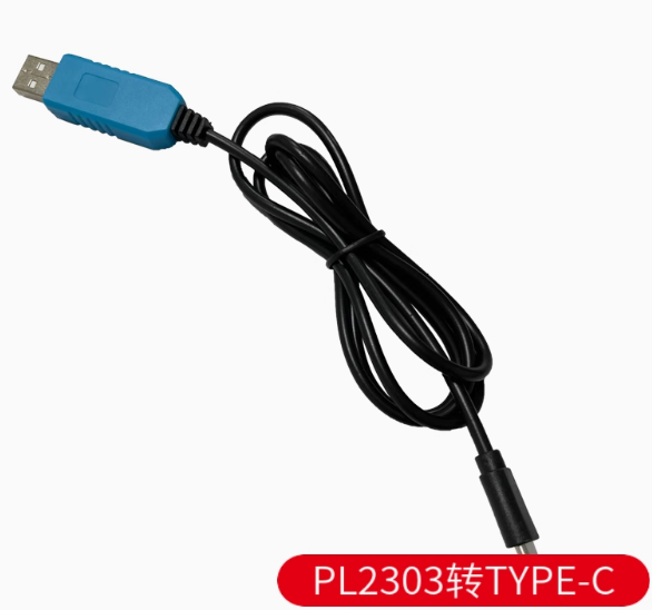
The Type-C Serial Adapter Module with PL2303 Onboard Chip is a modern, high-performance USB to UART (TTL) converter designed to bridge the gap between your computer’s USB Type-C port and microcontrollers, routers, and embedded systems. This adapter provides a reliable solution for programming, debugging, and serial communication with a wide range of devices.
Featuring the PL2303 series chip from Prolific Technology, this module delivers stable serial communication with support for both 3.3V and 5V logic levels, making it compatible with popular development boards such as Arduino, ESP8266, ESP32, STM32, and Raspberry Pi . The reversible USB Type-C connector ensures easy plug-in orientation and compatibility with the latest laptops, tablets, and smartphones.
The module includes onboard status LEDs (PWR, TXD, RXD) for real-time visual feedback of power and data transmission activity, simplifying troubleshooting and debugging . The VCCIO jumper setting allows flexible power configuration—you can power your target device directly from the adapter (3.3V or 5V) or have the target device supply the logic reference voltage (1.8V/2.5V/3.3V/5V) .
This adapter is an essential tool for electronics hobbyists, embedded systems developers, and network engineers who need to access console ports, flash firmware, or debug serial communication on modern computing devices that lack legacy USB-A ports.
Key Features
-
USB Type-C Connector: Modern reversible connector for easy plug-in; compatible with the latest laptops, tablets, and smartphones
-
PL2303 Chipset: Based on Prolific PL2303 series (GS/HXD variants) for stable USB-to-UART bridge performance
-
Adjustable Logic Level (VCCIO): Supports 1.8V, 2.5V, 3.3V, and 5V via onboard jumper—compatible with a wide range of target devices
-
3-in-1 Power Modes: Three operational modes via jumper setting:
-
3.3V Output: Short jumper to 3.3V pin
-
5V Output: Short jumper to 5V pin
-
External Power: Remove jumper, VCCIO powered by target board
-
Dual Power Supply Capability: The chip can be powered either by USB bus power (taking about 35mA) or by an external 3.3V supply
-
Status Indicator LEDs: Onboard PWR (power), TXD (transmit), and RXD (receive) LEDs for real-time communication monitoring
-
Full Duplex Asynchronous Communication: Supports data rates up to 12 Mbps with true full-duplex operation
-
Modem Control Signals: Provides full set of modem handshake signals (RTS, CTS, DSR, DTR, DCD, RI) and hardware flow control
-
Wide OS Compatibility: Supports Windows XP/7/8/10/11, macOS, and Linux; drivers available for all major platforms
-
Plug-and-Play: Hot-pluggable with automatic COM port configuration by the operating system
Technical Specifications
Pinout & Connection Guide
The module uses a standard 4-pin or 5-pin header (2.54mm pitch). Pin functions are clearly labeled on the PCB silk screen.
Jumper Configuration
Important Wiring Notes:
-
The TXD pin of the module connects to the RX pin of your target device
-
The RXD pin of the module connects to the TX pin of your target device
-
Always establish a common ground by connecting the GND pin
-
Select the correct VCCIO jumper setting before connecting to your target device
Usage Guide
Driver Installation
Windows Installation (PL2303 requires specific driver versions for compatibility) :
-
Download the latest PL2303 driver from the Prolific official website
-
Run the driver installer (PL2303_Prolific_DriverInstaller.exe)
-
Follow the installation wizard prompts
-
Connect the Type-C adapter to your computer
-
Verify installation in Device Manager → Ports (COM & LPT)
Important Driver Notes:
-
The newer PL2303GS/TA/HXD (Rev D) chips have full support for Windows 10/11
-
Older chips (HXA, X) have limited Windows 10/11 support and may require driver version 3.3.2.102
-
If you encounter a yellow exclamation mark, try using driver version 3.3.2.102 (dated 2008) or use automatic driver tools
macOS Installation:
-
Download the PL2303 driver from the manufacturer’s website
-
Install following the package instructions
-
The device will appear as /dev/cu.usbserial
Linux:
Loopback Test (Functional Test)
To verify the module is working correctly:
-
Set the VCCIO jumper to 3.3V or 5V as desired
-
Connect a jumper wire between TXD and RXD pins
-
Open a serial terminal program (e.g., PuTTY, Arduino Serial Monitor)
-
Select the module’s COM port, set baud rate to 115200, 8 data bits, 1 stop bit, no parity
-
Type characters—they should be echoed back to the terminal
-
Confirm both transmit and receive paths are functional
Common Applications
STC Microcontroller “Cold Start” Programming
When programming STC microcontrollers using this adapter:
-
Apply power to the target board
-
In STC-ISP software, select the correct COM port and baud rate (115200 typical)
-
Load your HEX file
-
Click Download/Program
-
Disconnect power from the target board
-
Reconnect power within about 2 seconds
-
Wait for “Operation Success” message
Power Supply Considerations
-
The VCCIO pin can provide either 3.3V or 5V (jumper selectable) to power your target device
-
When VCCIO is set to output power, the module draws power from USB VBUS
-
Typical power consumption is low (approximately 35mA for the chip)
-
For power-hungry devices (motors, servos, high-power LEDs), use a separate external power supply
-
When the VCCIO jumper is removed, the target device supplies the logic reference voltage (1.8V/2.5V/3.3V/5V)
Q: What is the difference between PL2303 and other USB-to-TTL chips like CH340 or CP2102?
The PL2303 from Prolific is one of the most widely used USB-to-UART bridge chips. It offers robust driver support across multiple operating systems, hardware flow control capabilities, and flexible voltage level options (1.8V–5V) . Compared to CH340, PL2303 generally offers better macOS support; compared to CP2102, it is often more readily available and cost-effective. The newer PL2303GS/HXD variants have improved Windows 10/11 compatibility .
Q: Is this Type-C module compatible with Windows 11?
Yes. The PL2303GS and PL2303HXD (Rev D) chips have official driver support for Windows 10 and 11 . If you have an older adapter with HXA/X chip, you may need to use driver version 3.3.2.102 or automatic driver tools .
Q: What is the maximum baud rate supported?
The PL2303 series supports baud rates from 300 bps up to 6 Mbps, with typical reliable operation up to 1 Mbps (921.6 Kbps). The Delock PL2303HXD adapter lists data transfer rates up to 921.6 Kbps .
Q: Can this module power my target device?
Yes. When the VCCIO jumper is set to 3.3V or 5V, the module provides regulated power output from the USB bus. This is sufficient for low-power microcontrollers. For devices requiring more than 500mA, use a separate external power supply .
Q: What voltage levels does this adapter support?
The VCCIO jumper allows you to set the logic reference voltage to 1.8V, 2.5V, 3.3V, or 5V . This makes the adapter compatible with a very wide range of target devices—from low-voltage FPGAs to 5V Arduino boards.
Q: Does this module include RTS/CTS hardware flow control?
Yes. The PL2303 chip provides full modem control signals including RTS, CTS, DTR, DSR, DCD, and RI. This enables reliable hardware flow control for high-speed data transfers or communication with devices that have limited buffers .
Q: My computer doesn't recognize the device. What should I do?
Follow this checklist:
-
Ensure drivers are properly installed (download from Prolific official website)
-
Try a different Type-C cable (ensure it’s a data cable, not charge-only)
-
Try a different USB port on your computer
-
Check Device Manager for yellow exclamation marks
-
For Windows 10/11, ensure you’re using a compatible PL2303 chip (GS/TA/HXD)
Q: Why does my PL2303 show a yellow exclamation mark in Device Manager?
This typically indicates a driver version mismatch. If you have an older PL2303 HXA or X chip, Windows 10/11 may not automatically find compatible drivers. Download driver version 3.3.2.102 (dated 2008) and manually install it through Device Manager: right-click the device → Update Driver → Browse my computer → Let me pick from a list → Select version 3.3.2.102 . Alternatively, use automatic driver tools like Driver Genius to scan and fix the issue.
Q: The TX/RX LEDs are not blinking. Is something wrong?
The LEDs blink only during data communication. At lower baud rates, they blink slower; at high baud rates (e.g., 115200+), they may appear dim or constantly lit due to the rapid flashing. If no data is being transmitted, the LEDs remain off. Test with a loopback connection to verify functionality .
Q: I'm getting garbage characters in my terminal. What's wrong?
Check the following:
-
Ensure baud rate matches your target device’s configuration (common: 115200, 9600, 57600)
-
Verify data bits (typically 8), stop bits (typically 1), and parity (typically None)
-
Check that TX and RX connections are not swapped
-
Try a lower baud rate to test basic communication
-
Verify the VCCIO voltage matches your target device’s logic level
Q: What can I build with this Type-C PL2303 module?
Popular applications include:
-
Microcontroller programming: Arduino, ESP8266, ESP32, STM32, STC series
-
Single-board computer console: Raspberry Pi, BeagleBone debug access
-
Router/Switch configuration: OpenWrt, DD-WRT firmware flashing, console access
-
GPS module interfacing: Reading GPS NMEA data on PC
-
Industrial equipment: Serial port access for PLCs, sensors, and instruments
-
DIY electronics: General debugging and serial communication testing
Q: Is this adapter suitable for router console access?
Yes. The PL2303 is widely used for accessing console ports on Cisco routers, switches, and other network equipment . For standard console ports (RS-232), you may need an additional level shifter (like MAX3232) because this module outputs TTL-level signals, not RS-232 (±12V) levels.
Q: Can I use this for Arduino programming?
Yes, but note that the 4-pin version (TXD/RXD/GND/VCCIO) may not include a DTR line for automatic reset. You will need to manually reset your Arduino board—press the reset button just as the upload begins. Some PL2303 modules include RTS/DTR lines in a 5-pin or 6-pin configuration for auto-reset support.
Q: Is this module compatible with Raspberry Pi?
Yes. The PL2303 is recognized on Raspberry Pi systems. Connect TXD → RXD (Pin 10), RXD → TXD (Pin 8), GND → GND (Pin 6). Use the built-in Linux drivers—no additional installation required. Do NOT connect the VCCIO power line to the Pi’s GPIO; power the Pi separately.
Q: What is the purpose of the VCCIO jumper? Why does the module have three power modes?
The VCCIO jumper sets the logic reference voltage for the UART interface :
-
3.3V mode: For 3.3V logic devices (ESP32, STM32, Raspberry Pi GPIO)
-
5V mode: For 5V logic devices (Arduino Uno, ATmega328P)
-
External mode: When the target device has a different logic voltage (1.8V/2.5V), remove the jumper and let the target supply VCCIO
This flexible design eliminates the need for external level shifters and ensures compatibility with virtually any microcontroller voltage level.