Product Overview
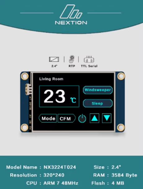
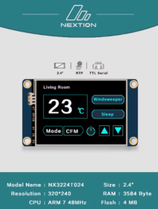
The Nextion NX3224K024 is a powerful, intelligent Human-Machine Interface (HMI) display module that integrates a 2.4-inch TFT LCD color screen with a resistive touch panel into a single, easy-to-use package . This “Enhanced” series model represents a significant upgrade over basic displays, incorporating a dedicated onboard processor that handles all graphical interface functions independently, freeing your main microcontroller (Arduino, ESP32, Raspberry Pi, STM32) to focus on core application tasks .
Unlike traditional LCDs that require complex parallel wiring and extensive graphics coding, the Nextion communicates via a simple 4-pin UART (Serial) interface using 5V TTL levels. This allows you to control the screen—drawing buttons, updating text, showing graphs, and detecting touches—using straightforward serial commands . The “Enhanced” version adds additional features like a real-time clock (RTC), General Purpose Inputs/Outputs (GPIO), and significantly expanded memory .
Whether you are building a smart home controller, an industrial machine interface, a medical device dashboard, or an IoT data terminal, the NX3224K024 provides a highly professional, plug-and-play visual interface that drastically reduces development time and complexity .
Key Features
-
Standalone HMI Processor: The display runs its own firmware. It does not rely on your main MCU to draw pixels. You simply send simple ASCII text commands over UART .
-
WYSIWYG GUI Editor: Design your interface by dragging and dropping components (buttons, gauges, sliders, text boxes, etc.) using the free, Windows-based Nextion Editor software. No low-level graphics programming is required .
-
Enhanced Series Advantages: Compared to basic Nextion models, the K024 features a faster CPU clock, larger Flash memory, additional GPIO pins, a built-in RTC, and EEPROM for storing user data .
-
Robust Display Specifications: A 320×240 resolution provides crisp, clear visuals for a 2.4″ screen, supporting vibrant 65K (16-bit) colors for rich graphics .
-
Simple Serial Communication: Uses a standard TTL UART (9600 bps default, up to 921600 bps). Connect the 4 pins (VCC, GND, TX, RX) directly to your microcontroller or USB-to-Serial adapter .
-
Integrated Resistive Touch Panel: Includes a durable resistive touch screen that registers input from a finger or stylus, with a lifetime exceeding 1 million touches .
-
Expandable I/O: The Enhanced series breaks out 8 digital GPIO pins (0-7) which can be used as inputs, outputs, or PWM outputs (on IO4-IO7) to control external hardware directly from the HMI interface .
-
microSD Card Slot: Easily upload your GUI designs (TFT files) and upgrade firmware via a microSD card (requires FAT32 formatting, up to 32GB) .
Technical Specifications
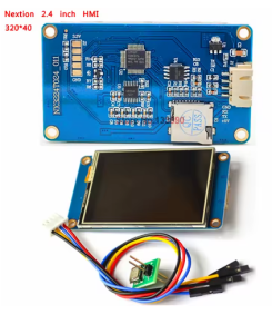
Pinout & Connection Guide
The module uses a simple 4-pin interface for all communication . The pin labeling is clearly marked on the back of the PCB.
Pin Definitions (4-Pin Header)
Wiring Diagrams
Connecting to Arduino Uno (5V):
Nextion NX3224K024          →    Arduino Uno
─────────────────────────────────────────────
VCC (5V)                    →    5V
TXD                         →    RX (Pin 0)
RXD                         →    TX (Pin 1)
GND                         →    GND
Connecting to ESP32 (3.3V):
Nextion NX3224K024          →    ESP32
─────────────────────────────────────────────
VCC (5V - external supply)  →    External 5V
TXD                         →    GPIO16 (RX2)
RXD                         →    GPIO17 (TX2)
GND                         →    GND
-
Note: The ESP32 operates at 3.3V, but the Nextion’s 5V TX will be seen as a valid HIGH signal. However, for reliability, some users prefer a level shifter or use the Nextion’s 3.3V output (not available on all pins). Power the Nextion from a stable external 5V supply, not from the ESP32’s 3.3V pin .
Connecting to USB-to-Serial Adapter (for PC Debugging):
Nextion NX3224K024          →    USB-to-TTL Adapter
─────────────────────────────────────────────
VCC (5V)                    →    5V
TXD                         →    RXD
RXD                         →    TXD
GND                         →    GND
Development & Usage Guide
1. Getting Started with Nextion Editor
Before using the display with your microcontroller, you must load your custom GUI design onto the screen .
-
Download Software: Download and install the Nextion Editor (available for Windows from the official Nextion website). This is the WYSIWYG software used to design your user interface .
-
Design Your GUI: Use the drag-and-drop interface to add components (buttons, text, sliders) to the canvas representing your screen.
-
Compile: Press F8 to compile the project. This generates a .tft file containing your design .
-
Upload to Display: Copy the .tft file to a microSD card (ensure it’s the only .tft file). Insert the card into the Nextion’s SD slot and power cycle the module. The new firmware will be flashed to the display. Remove the SD card afterward to prevent re-flashing .
2. Initial Communication & Baud Rate
Upon power-up with no functional TFT file, the display runs a demo. You must flash a blank or custom TFT file to communicate with it . By default, the Nextion communicates at 9600 baud. It is good practice to flush any spurious startup data from the UART buffer .
3. Basic Arduino Communication (Serial Commands)
Once your design is loaded, you can control the Nextion from your Arduino using simple print statements. Every command must end with three bytes of 0xFF (or \xFF\xFF\xFF).
Simple Interaction Example:
void setup() {
Serial1.begin(9600);
delay(2000);
}
void loop() {
Serial1.print("t0.txt=\"Hello World\"");
Serial1.write(0xFF); Serial1.write(0xFF); Serial1.write(0xFF);
delay(2000);
Serial1.print("b0.bco=63488");
Serial1.write(0xFF); Serial1.write(0xFF); Serial1.write(0xFF);
Serial1.print("b0.ref");
Serial1.write(0xFF); Serial1.write(0xFF); Serial1.write(0xFF);
delay(2000);
}
-
You can use the EasyNextionLibrary to simplify the sending of commands .
-
The writeStr function (from EasyNextion) handles the 0xFF terminators automatically. Example: myNex.writeStr("t0.txt", "Hello World"); .
4. Detecting Touch Events
When a button is pressed, the Nextion sends a touch event code (e.g., 65 0 1) out its TX pin. Your Arduino must read the serial buffer to detect these events.
if (Serial1.available() > 0) {
byte data = Serial1.read();
}
Q: What is the difference between the NX3224K024 and the NX3224T024?
The “K024” denotes the Enhanced series, while “T024” is the Basic series. The Enhanced model features a faster processor, a real-time clock (RTC), 8 GPIO pins (instead of 0), and more Flash/RAM memory, making it suitable for more complex standalone applications .
Q: Can I use this display with a 3.3V logic microcontroller (ESP32) without a level shifter?
The Nextion’s RX pin is 5V tolerant, but it outputs a 3.3V logic HIGH on its TX pin (tested typical). The ESP32’s 3.3V logic level is generally compatible with the Nextion’s input threshold, so you can connect them directly. However, the Nextion must be powered from a separate stable 5V source, not from the ESP32’s 3.3V pin .
Q: Why does the display not respond to my commands?
There are three common reasons: 1) The demo firmware is still loaded (you must flash your own .tft file) . 2) Your commands are not terminated correctly (you must send three 0xFF bytes) . 3) The baud rates of your microcontroller’s Serial port and the Nextion do not match (default is 9600).
Q: How do I change the baud rate of the Nextion display?
You can change the baud rate by sending the command baud=115200 followed by the three-byte terminator (0xFF 0xFF 0xFF). You must also immediately change your microcontroller’s Serial port baud rate to match, or communication will break.
Q: What is the purpose of the microSD card slot?
The microSD card slot is primarily used for uploading your firmware (.tft file) to the Nextion’s internal flash memory . The slot can also be used to store bitmap images (.jpg files) that you host on an SD card for the display to access. It is not used for data logging directly by a host MCU.
Q: How much memory does the Enhanced series have?
The NX3224K024 has 16 MB of Flash memory for storing resources (fonts, images, etc.), 1024 bytes of non-volatile EEPROM, 3584 bytes of RAM, and a 1024-byte instruction buffer .
Q: The display is flickering or showing corrupt images. What is wrong?
This is most often a power supply issue. The Nextion draws about 90 mA of current, with higher peaks during startup. Ensure your power supply is capable of supplying a stable 5V at 500mA. Also, check that the VCC and GND wires are securely connected and not loose .
Q: Is the Nextion truly "standalone" or does it always need a host MCU?
The Nextion is a smart display. It can run its logic using its built-in processor, GPIO, and RTC to a limited extent. However, for most IoT or complex control projects, it acts as a slave device, with an external MCU (Arduino, ESP32) sending it commands and receiving touch events . The Nextion handles the user interface; the MCU handles the application logic.