Product Overview
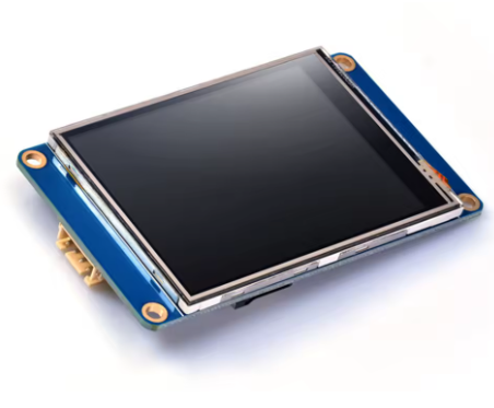
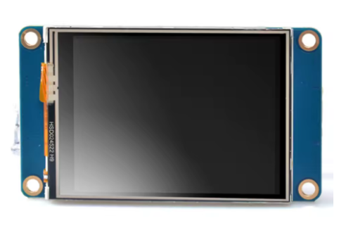
The Nextion Basic NX4832T035 is a powerful, intelligent Human-Machine Interface (HMI) display module that combines a 3.5-inch TFT LCD color screen with a resistive touch panel into a single, easy-to-use package . Designed to provide a seamless control and visualization interface, this Basic series display is the ideal solution for IoT applications, consumer electronics, industrial automation, and embedded projects.
What sets the Nextion apart from traditional LCDs is its intelligent architecture. Unlike standard displays that require your main microcontroller to handle all graphics rendering, the NX4832T035 features a dedicated onboard processor (running at 48MHz) that independently manages all graphical interface functions—drawing buttons, updating text, displaying graphs, processing touch inputs, and managing screen transitions . Your host microcontroller (Arduino, ESP32, Raspberry Pi, STM32) communicates with the display using simple ASCII text commands over a standard UART (TTL serial) interface . This approach eliminates the need for complex graphics programming and parallel wiring, dramatically reducing development time.
The free, drag-and-drop Nextion Editor software allows you to design your graphical user interface visually without writing a single line of graphics code. Simply place components onto the canvas, assign properties, and compile . The WYSIWYG environment reduces GUI development workload by up to 99% compared to traditional methods.
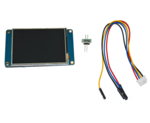
Each package includes a power supply test board that allows you to verify your power supply can deliver enough current before connecting the display, preventing damage from insufficient power .
Key Features
-
3.5-Inch TFT LCD Display: 480 × 320 pixel resolution (also configurable as 320×480) with 65,536 colors (16-bit RGB 565), providing vivid, true-to-life visuals
-
Resistive Touch Panel: Durable 4-wire resistive touch screen rated for over 1 million touches; responds to finger, gloved hand, or stylus input
-
Intelligent Standalone Operation: Onboard 48MHz MCU handles all graphics and touch processing independently—your host MCU only needs to send simple commands
-
Simple Serial Communication: 4-pin UART interface (VCC, GND, TX, RX) using TTL 3.3V/5V tolerant logic—connects directly to Arduino, ESP32, Raspberry Pi, or STM32
-
Free WYSIWYG GUI Editor: Nextion Editor software with 25+ drag-and-drop components (buttons, text boxes, sliders, progress bars, gauges, timers) and built-in simulator for debugging without hardware
-
Adjustable LED Backlight: Brightness adjustable from 0% to 180 nits in 1% increments via simple serial command
-
Built-in Flash Storage: 16MB flash memory for storing fonts, images, and HMI program data; 3584 bytes RAM for variables
-
microSD Card Slot: For easy firmware updates (TFT file upload). Supports FAT32 format, up to 32GB
-
Wide Operating Voltage Range: Accepts 4.75V to 7.0V DC (5V typical), with operating current of 145mA (normal) and 15mA (sleep mode)
Technical Specifications
Pinout & Connection Guide
The module uses a simple 4-pin, 2.54mm pitch header for all communication and power. The pinout is clearly marked on the back of the PCB.
Pin Definitions
Wiring Diagrams
Arduino Uno / Mega (5V logic):
NX4832T035              →    Arduino Uno
──────────────────────────────────────────────
VCC                     →    5V
TXD                     →    RX (Pin 0)
RXD                     →    TX (Pin 1)
GND                     →    GND
ESP32 (3.3V logic):
NX4832T035              →    ESP32 / Raspberry Pi
──────────────────────────────────────────────
VCC                     →    5V supply (external – not from ESP32!)
TXD                     →    RX pin (GPIO16 for ESP32, Pin 10 for RPi)
RXD                     →    TX pin (GPIO17 for ESP32, Pin 8 for RPi)
GND                     →    GND
Note: The Nextion requires a stable 5V supply capable of delivering 500mA. The ESP32’s 3.3V pin cannot power the display .
Usage Guide
1. Power Supply Testing (Critical First Step)
IMPORTANT: Insufficient power supply is a common cause of Nextion display damage . The included power supply test board allows you to verify your power supply before connecting the display. Test your power source with the provided test board. If the test board indicator functions correctly, your power supply is adequate.
Always use a high-quality 5V USB power source rated for at least 500mA. Do not power the display from your microcontroller’s 3.3V pin .
2. Nextion Editor Software
Design your HMI interface using the free Nextion Editor software, available for download from the official Nextion website .
Basic Workflow:
-
Launch Nextion Editor and click “New”
-
Select “Basic” as the series and choose “NX4832T035” as the model
-
Drag components (buttons, text boxes, sliders, progress bars, gauges, timers) onto the page canvas
-
Configure component properties (colors, text, size, position, etc.)
-
For interactive components, enable “Send Component ID” in the Event pane to allow your host MCU to detect touch events
-
Set communication baud rate—add bauds=115200 (or your desired rate) to the Preinitialize Event of the first page
-
Press F8 to compile the project and generate a .tft firmware file
3. Uploading Firmware to the Display
Recommended Method: microSD Card
-
Format a microSD card as FAT32 (maximum 32GB)
-
Copy the compiled .tft file to the root directory of the SD card
-
Ensure the card contains only one .tft file
-
Power off the Nextion display
-
Insert the microSD card into the display’s slot
-
Power on the display—firmware uploads automatically
-
After “Update Success!” message appears, power off
-
Remove the microSD card before powering on again
4. Host MCU Communication (Arduino Example)
Once your GUI is loaded, control the display from your microcontroller using simple print statements. Important: Every command sent to the Nextion must end with three bytes of 0xFF (the command terminator) .
void setup() {
Serial.begin(115200);
delay(3000);
}
void loop() {
Serial.print("t0.txt=\"Hello World\"");
Serial.write(0xFF); Serial.write(0xFF); Serial.write(0xFF);
delay(2000);
static int counter = 0;
counter++;
Serial.print("n0.val=");
Serial.print(counter);
Serial.write(0xFF); Serial.write(0xFF); Serial.write(0xFF);
delay(1000);
}
5. Using the Iteadlib Arduino Library
The ITEADLIB_Arduino_Nextion library simplifies communication by handling the 0xFF terminators automatically.
Installation:
-
Download the library ZIP from GitHub
-
In Arduino IDE: Sketch → Include Library → Add .ZIP Library
Basic Library Example:
#include "Nextion.h"
NexText t0 = NexText(0, 1, "t0");
NexNumber n0 = NexNumber(0, 2, "n0");
void setup() {
nexInit();
}
void loop() {
t0.setText("Hello");
n0.setValue(42);
delay(1000);
}
6. ESP32 / Raspberry Pi Notes
When using the ESP32, configure the library for hardware Serial2:
In NexConfig.h, modify:
#define nexSerial Serial2
For Raspberry Pi, you can connect the Nextion directly to the GPIO UART pins (GPIO14=TX, GPIO15=RX) using a 5V power supply .
Q: What is the difference between the Basic Series (NX4832T035) and the Enhanced Series (NX4832K035)?
The Basic Series (NX4832T035) is designed for standard HMI applications requiring display and touch functionality. It features a 48MHz MCU, 16MB flash, and 3584 bytes RAM. The Enhanced Series adds a faster processor, Real-Time Clock (RTC), EEPROM, GPIO pins, and larger memory . Basic series projects will not work on Enhanced displays due to memory and feature differences .
Q: Can I use this display with a 3.3V logic microcontroller like ESP32 without a level shifter?
The Nextion’s RXD pin is 5V tolerant and accepts 3.3V logic signals. The TXD pin outputs 3.3V logic, which is compatible with most 3.3V microcontrollers . However, the VCC pin must be powered by a separate 5V supply capable of delivering 500mA—do not power the display from your microcontroller’s 3.3V pin .
Q: Why is my display not responding to commands?
Check these common issues:
-
No firmware loaded: The display must have a valid .tft file flashed—the factory demo may not respond to commands
-
Incorrect command termination: Every command must end with three bytes of 0xFF
-
Baud rate mismatch: The default baud rate is 9600; ensure your code matches. Change it with bauds=115200 in the HMI project
-
Power supply: Ensure your 5V power supply delivers at least 500mA
Q: How do I change the baud rate of the Nextion display?
In your Nextion Editor project, add the command bauds=115200 (or your desired rate—up to 921600 bps) to the Preinitialize Event of your first page . This sets the communication speed when the display boots. Remember to also change your microcontroller’s Serial port baud rate to match.
Q: What is the microSD card used for?
The microSD card slot is exclusively for upgrading the Nextion’s firmware (uploading your .tft GUI file) . The display cannot read files from the SD card during normal operation—it is for programming only. Use FAT32 format, maximum 32GB.
Q: Can the Nextion display operate without a host microcontroller?
The Nextion Basic series can display static screens and respond to touch events, but for dynamic data updates and complex logic, it requires a host microcontroller (Arduino, ESP32, etc.) to send commands and process touch events .
Q: How do I detect button presses on the Nextion?
In the Nextion Editor, select your button component. In the Event pane, check the “Send Component ID” checkbox for the “Push” or “Release” event . Your microcontroller will receive a code (e.g., 65 0 1 for button 1 on page 0) when the button is touched.
Q: What is the purpose of the included power supply test board?
The power supply test board allows you to verify your power source can deliver adequate current before connecting the display. Insufficient power is a common cause of Nextion damage . Test your power source with the included test board first.
Q: Why is my display flickering or showing corrupt graphics?
This is almost always a power supply issue. The NX4832T035 draws about 145mA at 100% brightness, with higher current spikes during startup . Ensure your power supply provides a stable 5V at 500mA. Check that VCC and GND wires are securely connected.
Q: Can I use multiple Nextion displays with one microcontroller?
Yes, but each display requires its own UART port. Use different serial ports on your microcontroller for each display. You cannot share a single UART between multiple displays, but you can send commands to specific displays using their unique serial connections.