Product Overview
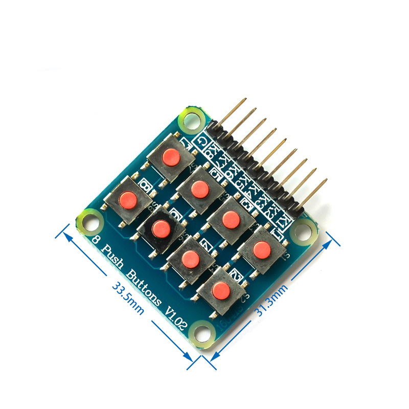
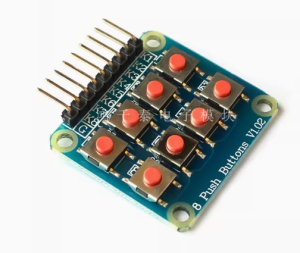
The 2×4 Matrix Keyboard Module is a compact and efficient input device featuring 8 independent tactile micro-switches arranged in a 2-row by 4-column matrix configuration . This module is specifically designed as an external keyboard expansion for single-chip microcomputers, providing a convenient alternative to using eight separate tact switches .
The matrix design is key to its efficiency. By arranging the 8 keys in rows and columns, the module requires only 6 I/O pins (2 rows + 4 columns) to read all 8 buttons, rather than 8 individual pins. This matrix scanning approach significantly conserves your microcontroller’s valuable GPIO resources, making it an excellent choice for projects where I/O pins are limited .
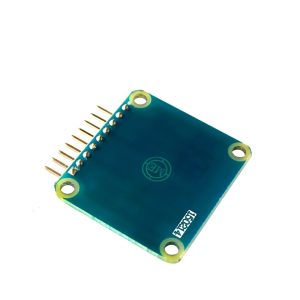
Pre-soldered pin headers on the module allow for immediate breadboard or jumper wire connection, eliminating the need for soldering . The PCB includes four 3mm mounting holes, enabling secure attachment to enclosures, robot chassis, or prototyping platforms.
Whether you are building a custom control panel for a robot, designing a numeric keypad for a DIY calculator, creating a menu selection interface for an automation project, or teaching students the fundamentals of keyboard scanning, this 2×4 matrix keyboard module provides a simple, reliable, and space-saving solution for direct user input to your Arduino, ESP32, STM32, or other microcontroller projects.
Key Features
-
1×2 Matrix Layout: 8 individual tactile micro-switches arranged in 2 rows and 4 columns for intuitive numeric and functional input
-
I/O Efficient Matrix Design: Requires only 6 GPIO pins (2 rows + 4 columns) to read 8 buttons, significantly reducing pin usage from 8 individual pins
-
Tactile Micro-Switches: Quality pushbuttons provide positive tactile feedback with each press
-
Pre-Soldered Male Header Pins: Ready to insert into breadboards or connect with female-to-female jumper wires – no soldering required
-
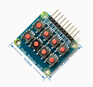
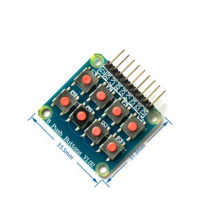
Compact & Portable: Small footprint (approx. 34mm × 32mm) fits easily into tight project enclosures and is very easy to carry
-
Standard 2.54mm (0.1″) Pin Spacing: Compatible with standard breadboards, perfboards, and Dupont jumper wires
-
Mounting Holes: Four 3mm (M3) holes for secure attachment to cases, robot chassis, or panels
-
Clear Function Markings: Silkscreen labels on the PCB indicate each key’s position and connection points, simplifying wiring
Technical Specifications
Pinout & Connection Guide
Pin Definitions
The module uses a 6-pin interface. The exact order of row and column pins may vary between manufacturers; always verify the silkscreen on your specific board.
Wiring to Arduino Uno
How the Matrix Works
In a matrix keyboard, each key connects a specific row and column . When no key is pressed, all row and column lines are electrically isolated. When a key is pressed, it connects its row and column lines together, creating a closed circuit that the microcontroller can detect by scanning the matrix.
The microcontroller activates one row at a time (sets it HIGH) and reads the states of all column pins. If a key in that row is pressed, the corresponding column pin will read HIGH. By quickly cycling through all rows and checking all columns, the microcontroller can determine exactly which key (if any) is pressed – all using just rows + columns I/O pins .
Usage Guide
Software Setup (Arduino IDE)
Step 1: Install the Keypad Library
The Keypad library by Mark Stanley and Alexander Brevig handles all matrix scanning and debouncing automatically.
-
Open Arduino IDE → Sketch → Include Library → Manage Libraries
-
Search for “Keypad”
-
Find the library by Mark Stanley, Alexander Brevig and click Install
Step 2: Basic Test Sketch
#include <Keypad.h>
const byte ROWS = 2;
const byte COLS = 4;
char keys[ROWS][COLS] = {
{'1','2','3','4'},
{'5','6','7','8'}
};
byte rowPins[ROWS] = {9, 8};
byte colPins[COLS] = {7, 6, 5, 4};
Keypad keypad = Keypad(makeKeymap(keys), rowPins, colPins, ROWS, COLS);
void setup() {
Serial.begin(9600);
Serial.println("2x4 Matrix Keyboard Ready. Press any key...");
}
void loop() {
char key = keypad.getKey();
if (key) {
Serial.print("Key Pressed: ");
Serial.println(key);
switch(key) {
case '1':
break;
case '2':
break;
}
}
}
Step 3: Connecting Without the Library
If you prefer not to use the library, you can implement matrix scanning yourself:
int rowPins[] = {9, 8};
int colPins[] = {7, 6, 5, 4};
void setup() {
Serial.begin(9600);
for (int i = 0; i < 2; i++) {
pinMode(rowPins[i], OUTPUT);
digitalWrite(rowPins[i], LOW);
}
for (int i = 0; i < 4; i++) {
pinMode(colPins[i], INPUT_PULLUP);
}
}
void loop() {
for (int row = 0; row < 2; row++) {
digitalWrite(rowPins[row], HIGH);
for (int col = 0; col < 4; col++) {
if (digitalRead(colPins[col]) == LOW) {
int keyNumber = row * 4 + col + 1;
Serial.print("Key ");
Serial.println(keyNumber);
delay(200);
}
}
digitalWrite(rowPins[row], LOW);
}
delay(50);
}
Raspberry Pi (Python) Setup
For Raspberry Pi, you can use the pad4pi library:
from pad4pi import rpi_gpio
import time
KEY_MAP = [
["1", "2", "3", "4"],
["5", "6", "7", "8"]
]
ROW_PINS = [9, 8]
COL_PINS = [7, 6, 5, 4]
factory = rpi_gpio.KeypadFactory()
keypad = factory.create_keypad(keypad=KEY_MAP, row_pins=ROW_PINS, col_pins=COL_PINS)
def print_key(key):
print(f"Key Pressed: {key}")
keypad.registerKeyPressHandler(print_key)
try:
while True:
time.sleep(0.1)
except KeyboardInterrupt:
keypad.cleanup()
Q: How many I/O pins does this module require on my microcontroller?
The matrix design requires 6 I/O pins: 2 row pins and 4 column pins . This is significantly more efficient than connecting 8 independent switches, which would require 8 individual pins.
Q: Can I use this module with a 3.3V microcontroller like ESP32 or Raspberry Pi?
Yes, the module works with both 3.3V and 5V logic systems. The micro-switches are passive components, so voltage compatibility depends on your pull-up configuration. For 3.3V systems, enable internal pull-ups (INPUT_PULLUP) or use external 4.7kΩ – 10kΩ resistors to VCC (3.3V).
Q: How do I know which pin is for which row or column?
The PCB typically has silkscreen labels indicating R1, R2, C1, C2, C3, C4. If the labels are not present, use a multimeter in continuity mode to trace which pins connect to which keys and determine the matrix layout.
Q: What is the "matrix" design and why is it used?
The matrix design arranges switches in a grid of rows and columns . Instead of each key having its own dedicated input pin, the microcontroller scans the grid by activating one row at a time and reading the columns. This allows 8 keys to be read using only 6 pins instead of 8.
Q: Can I connect more than one of these modules to a single microcontroller?
Yes, but each module requires its own set of row and column pins. If you need many keys, consider an 8×8 matrix or use an I/O expander (like PCF8574 or MCP23017) to communicate via I2C, which uses only 2 pins regardless of how many keys you add.
Q: Why does my keypad register random or multiple presses?
This is usually contact bounce. Mechanical switches “bounce” when pressed, creating multiple rapid signal changes. The solution is debouncing – ignoring signals for a short period (typically 10-50ms) after the first detection. The Keypad library includes built-in debouncing, or you can implement delay-based debouncing in your code.
Q: Can I change what each key does without changing the wiring?
Absolutely! The key mapping is defined entirely in software. In the keys[][] array, you can assign any characters or values to each button position – letters, numbers, commands, or function calls. The physical wiring only determines which button is connected to which row/column intersection.
Q: What is the purpose of the mounting holes?
The four 3mm holes allow you to securely screw the module into enclosures, project boxes, robot chassis, or control panels . This prevents the module from moving around during use and ensures reliable operation.
Q: Does this module have pull-up resistors included?
Most basic matrix keyboard modules do not include onboard pull-up resistors. You should enable the microcontroller’s internal pull-ups using pinMode(pin, INPUT_PULLUP) in Arduino, or add external 4.7kΩ – 10kΩ resistors for more reliable operation, especially with longer wires.
Q: What's the difference between a matrix keypad and independent switches?
Matrix Keypad: Shares rows and columns, requires scanning logic, uses fewer pins, best for many buttons (8-64+). Independent Switches: Each switch has its own pin, no scanning required, simple code but uses many pins. This module uses the matrix design for pin efficiency while being compact and easy to use .