Product Overview
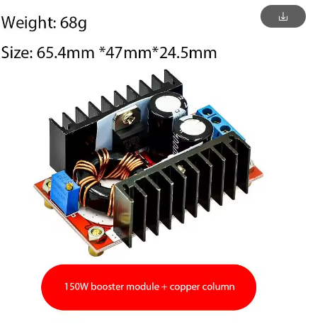
The 150W High-Power DC-DC Boost Converter Module is a professional-grade step-up voltage regulator engineered to efficiently convert a lower DC input voltage (10-32V) into a higher, user-adjustable DC output (12-35V). The defining feature of this advanced model is its integrated copper pillar heat dissipation system, which dramatically enhances thermal performance compared to standard boost converter modules . This design allows the module to reliably deliver up to 150W of output power (with enhanced cooling), making it a robust solution for demanding applications such as laptop charging from a car battery, powering 24V industrial equipment from a 12V source, driving high-voltage LED arrays, and boosting solar power for advanced battery charging .
Unlike standard buck-boost modules that switch at lower frequencies, this high-power unit operates at a high switching frequency, which, when combined with the efficient copper pillar heat sinks, ensures superior thermal management and consistent performance even under heavy loads. This module is a perfect upgrade for projects that require reliable high-power delivery, where excess heat can lead to component failure or reduced efficiency .
Key Features
-
Industrial-Grade Heat Dissipation: Features robust copper pillar heat sinks directly mounted to the main switching components (MOSFETs and rectifier). This provides a highly efficient thermal path, allowing for sustained high-power operation (up to 150W) without overheating .
-
High 150W Output Capacity: Capable of delivering a maximum output power of 150W (with enhanced cooling) and 100W under natural convection. This provides ample power for laptops, industrial controllers, LED systems, and motor drivers .
-
Wide Adjustable Voltage Range: Input from 10V to 32V DC and provides a continuously adjustable output from 12V to 35V DC. An onboard multi-turn potentiometer allows for precise voltage setting to match your specific device requirements .
-
High-Efficiency Conversion: Achieves a peak conversion efficiency of 94% (e.g., at 16V input, 19V output, 2.5A load). This ensures minimal power is wasted as heat, maximizing battery life and reducing thermal stress on the module .
-
Built-in Heatsink & Fan Support: Pre-installed with an aluminum heatsink and includes mounting points for an optional 12V cooling fan. This modular cooling system allows you to scale the thermal performance based on your load demands .
-
Durable Screw Terminal Block: Features large, reliable screw terminals for secure and low-resistance connections for both the input and output power wires, rated to handle high currents safely .
-
LED Status Indicator: An onboard LED provides a clear visual confirmation when the module is powered on, which is useful for quick system checks .
Technical Specifications
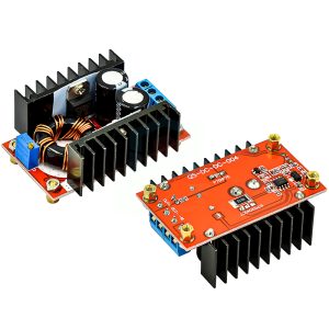
Pinout & Connection Guide
The module uses a clearly labeled 4-terminal screw block connection system for robust and secure wiring.
Input Terminals (Power Source)
-
VIN+ / IN+ (Positive Input): Connect to the positive terminal of your DC power source (e.g., 12V battery, power supply).
-
VIN- / GND (Negative Input): Connect to the negative terminal (ground) of your power source.
Output Terminals (Load Connection)
-
VOUT+ / OUT+ (Positive Output): Connect to the positive terminal of your device (e.g., laptop, LED strip, motor).
-
VOUT- / GND (Negative Output): Connect to the negative terminal (ground) of your device.
User Adjustments & Features
-
Potentiometer (CV Adj): A blue multi-turn trimmer potentiometer. Turn it clockwise to increase the output voltage; turn it counter-clockwise to decrease it. Always adjust with a multimeter connected to the output.
-
Cooling Fan Header: A 2-pin header (typically JST or screw terminal) for connecting a 12V fan to enable active cooling for 150W operation.
-
Power Indicator LED: Illuminates when the input power is connected and the module is active.
⚠️ Critical Safety Warning: No Built-In Protections
This module does NOT have short circuit protection or reverse polarity protection. You MUST install an external fuse (10A-15A fast-blow) in series with the input positive line to prevent fire or catastrophic failure in case of a short circuit. Double-check all connections for correct polarity before applying power.
Usage Guide
Important Preliminary Steps
⚠️ Use a Multimeter: The factory default output is often set to a high voltage (e.g., 20-24V). Always measure the output with a multimeter before connecting your load. Adjust the potentiometer to the exact voltage required by your device to avoid damage.
Wiring Instructions
-
Install Protection (Critical): Before connecting the module to your main power source, wire an in-line fuse holder with a 10A-15A fast-blow fuse on the positive input wire.
-
Set Initial Output Voltage: With the power source OFF, connect your multimeter to the output terminals. Turn the potentiometer counter-clockwise 10-15 turns to set it to the minimum voltage.
-
Connect Input Power: Connect your DC power source (10-32V) to the IN+ and IN- terminals. Ensure correct polarity. The LED should illuminate.
-
Adjust Output Voltage: Turn the potentiometer clockwise while watching your multimeter. Stop when you reach your desired output voltage (e.g., 19V for a laptop, 24V for an LED strip).
-
Connect Load: Turn off input power, connect your load to the OUT+ and OUT- terminals, and then re-apply power.
Power De-Rating & Thermal Management
The maximum output power depends entirely on the cooling solution you provide:
Tip: At full 150W load, the module will generate significant heat. An active fan is mandatory for reliable 150W operation. The copper pillar heat sink is designed to wick heat away from the MOSFETs, but this heat must be carried away by sufficient airflow .
Typical Applications
Q: What is the advantage of "Copper Pillar Heat Dissipation"?
Standard modules often rely solely on a flat heatsink. The copper pillars act as highly efficient thermal conduits, directly transferring heat from the hottest components (the power MOSFETs) up into the finned heatsink. This reduces the thermal resistance between the silicon junction and the ambient air, allowing for sustained high-power operation and preventing thermal shutdown
Q: Why does my output voltage drop when I connect a heavy load?
This is typically due to a voltage drop in the input wiring or an inadequate power supply. When the load increases, the input current also increases, causing a voltage drop across long or thin input wires. Solution: Use thick, short wires (12-14 AWG) for both input and output connections.
Q: Why does my connected laptop not charge or the device not turn on?
A common reason is insufficient peak current delivery. Some laptops require a high “inrush” current to start charging. The module may current-limit, causing a voltage drop. Solutions: Add a large (e.g., 1000-2200µF) low-ESR capacitor across the output terminals, or ensure your input battery can deliver sustained current.
Q: Is the output isolated from the input?
No. This is a non-isolated BOOST converter. The input and output share a common ground. Do not use this module for applications that require galvanic isolation between the source and the load.
Q: Can I use a lower voltage than 10V as an input?
The module requires a minimum of 10V to start and operate correctly. If the input voltage drops below this threshold (e.g., an old battery under load), the output may become unstable or shut down. For 24V outputs, a 12V input is generally recommended.
Q: What is the purpose of the capacitor on the output?
The internal ceramic capacitors are for high-frequency filtering. For high-power applications, especially those with dynamic loads (like laptops or motors), adding a large electrolytic capacitor (e.g., 470µF to 2200µF) on the output terminals helps absorb transient spikes and provides a reservoir of energy, improving stability .
Q: Why is the idle current 25mA? Will it drain my battery?
The control circuitry draws a small amount of power (~25mA) even when no load is connected. This is normal for a switching regulator. If left connected to a car battery for a month, it would drain about 18Ah of capacity, so it is advisable to disconnect it when not in use for long periods .
Q: Can I use this as a battery charger (e.g., for 24V LiFePO4)?
With caution. This is a Constant Voltage (CV) power supply. A lithium battery requires a Constant Current/Constant Voltage (CC/CV) charging profile. You can use this as the front-end power supply, but you must add a constant current regulator or use a dedicated Battery Management System (BMS) between this module and the battery to ensure safe charging.
Q: What is the orientation of the cooling fan?
The fan should be mounted so it blows air onto the heatsink fins. This forced convection is critical for achieving the maximum 150W power rating, as natural convection is insufficient at that power level .
Q: How do I get 150W output reliably?
To achieve 150W, you must:
-
Provide an input voltage and current capable of delivering 150W + 10% (e.g., 12V @ 14A).
-
Install and power a 12V cooling fan as active cooling is mandatory.
-
Use thick, low-resistance wires (12-14 AWG) for both input and output connections .
-
Ensure the ambient temperature is below 40°C for full power operation .