Product Overview
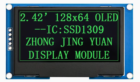
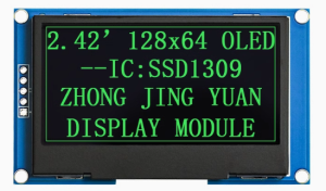
The 2.42-inch Passive Matrix OLED Display Module is a large-format, high-contrast monochrome graphic display designed for embedded systems, IoT devices, and industrial applications. Powered by the SSD1309 driver IC and featuring a crisp 128×64 pixel resolution, this display delivers bright green text, detailed graphics, and custom icons on a true black background, all in a spacious 2.42-inch diagonal format – significantly larger than the common 0.96-inch and 1.3-inch OLEDs.
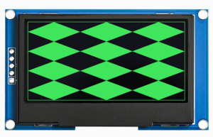
OLED (Organic Light Emitting Diode) technology requires no backlight, as each pixel emits its own light. This self-emissive design provides true blacks (inactive pixels are completely off), an exceptional contrast ratio of 10,000:1, and wide viewing angles – ensuring the display remains readable from virtually any angle while consuming minimal power.
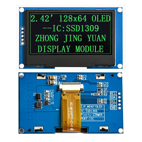
This module features a dedicated RES (reset) pin for hardware display initialization and is factory-configured for I2C interface, requiring only two data lines (SDA and SCL) to connect to your microcontroller. The 5-pin layout (GND, VCC, SCL, SDA, RES) is compatible with most development boards and can be used directly with standard 4-pin I2C connections by tying the RES pin HIGH .
With support for both 3.3V logic, it is directly compatible with ESP32, ESP8266, STM32, Raspberry Pi, and other 3.3V development boards. For 5V systems (Arduino Uno), the module’s I2C lines are 5V tolerant, making it safe for direct connection .
Key Upgrade over SSD1306 Displays: Unlike the common 0.96″ SSD1306 displays, this 2.42″ module uses the SSD1309 controller, which features higher row drive current (40mA vs 15mA) needed for larger panels. This means your 2.42″ display will be noticeably brighter and more consistent across the entire screen compared to smaller OLEDs .
Key Features
-
Large 2.42-Inch Active Area: 55.01 × 27.49mm display area – approximately 6 times larger than 0.96″ OLEDs, providing significantly more screen real estate for dashboards, data visualization, and UI elements
-
Green Monochrome OLED: Bright green pixels on true black background provide excellent contrast (10,000:1) and a classic terminal-style appearance
-
SSD1309 Driver IC: Advanced controller specifically designed for larger OLED panels, featuring higher row drive current for superior brightness uniformity, 256-step contrast control, and internal SRAM buffer (128 × 64 bits)
-
I2C Interface: 5-pin connection (GND, VCC, SCL, SDA, RES) – requires only 2 data lines (SDA/SCL) with default address 0x3C, saving valuable GPIO pins
-
Dedicated RESET Pin: Hardware reset pin allows external control of display initialization for reliable startup and recovery
-
Wide Operating Temperature: Rated for -40°C to +80°C, suitable for industrial and outdoor applications
-
Low Power Consumption: Only lit pixels consume power – typically 18-22mA when the display is active, making it ideal for battery-powered projects
-
5V/3.3V Dual Voltage Compatibility: I2C logic is 5V tolerant; works with both 3.3V (ESP32/ESP8266) and 5V (Arduino) systems
Technical Specifications
Pinout & Connection Guide
The module features a 5-pin interface. Pin order may vary between manufacturers – always verify the silkscreen on your specific module.
Pin Definitions (5-Pin – Confirmed for This Module)
⚠️ Critical Wiring Note: The module you linked (5-Pin, GND/VCC/SCL/SDA/RES) is not the same arrangement shown in some 7‑pin reference diagrams. Use the 5‑pin pinout above for your exact module.
Connection to 3.3V Microcontrollers (ESP32, ESP8266, Raspberry Pi – Recommended)
I2C lines are 3.3V logic. GPIO RES pin can be any available GPIO.
Connection to 5V Systems (Arduino Uno)
The I2C lines on this module are 5V tolerant, so you can connect them directly to a 5V Arduino without level shifters. However, VCC must be 3.3V .
I2C Address Configuration
Most SSD1309 modules are configured for I2C address 0x3C (7‑bit) by default, which corresponds to 0x78 (write)/0x79 (read). Some modules support address 0x3D via resistor configuration . Run an I2C scanner to verify the address of your specific module.
Usage Guide
Power Supply Considerations
⚠️ Important: This 2.42″ module draws significantly more current than smaller OLEDs (up to ~300mA peak) . Ensure your power source can deliver adequate current, especially if using other peripherals.
Software Setup (Arduino IDE)
Step 1: Install Required Libraries
Install the following libraries via Arduino Library Manager (Sketch → Include Library → Manage Libraries):
-
“U8g2” by Oliver Kraus – Most reliable for SSD1309, extensive font support, auto‑handles memory
-
“Adafruit GFX Library” + “Adafruit SSD1306” – Note: The SSD1306 library may require small changes for SSD1309.
Library Note for SSD1309: The SSD1309 is command‑compatible with the SSD1306, but some advanced commands differ. The Adafruit_SSD1306 library may need a patch for the larger 2.42″ panel – the U8g2 library is generally better tested for the SSD1309.
Step 2: Basic Test Sketch (U8g2 – Recommended)
#include <Arduino.h>
#include <U8g2lib.h>
#include <Wire.h>
U8G2_SSD1309_128X64_NONAME0_F_HW_I2C u8g2(U8G2_R0, U8X8_PIN_NONE);
void setup() {
u8g2.begin();
u8g2.enableUTF8Print();
u8g2.setFont(u8g2_font_ncenB08_tr);
u8g2.setDrawColor(1);
}
void loop() {
u8g2.firstPage();
do {
u8g2.drawStr(0, 15, "2.42 OLED");
u8g2.drawStr(0, 35, "128x64");
u8g2.drawStr(0, 55, "SSD1309 - I2C");
u8g2.drawStr(0, 75, "Green Display");
} while ( u8g2.nextPage() );
delay(1000);
}
Step 3: Alternative using Adafruit Library
If you prefer simpler syntax, use the Adafruit_SSD1306 library (with patch for 2.42″ screen):
#include <Wire.h>
#include <Adafruit_GFX.h>
#include <Adafruit_SSD1306.h>
#define SCREEN_WIDTH 128
#define SCREEN_HEIGHT 64
#define OLED_RESET -1
Adafruit_SSD1306 display(SCREEN_WIDTH, SCREEN_HEIGHT, &Wire, OLED_RESET);
void setup() {
display.begin(SSD1306_SWITCHCAPVCC, 0x3C);
display.clearDisplay();
display.setTextSize(1);
display.setTextColor(SSD1306_WHITE);
display.setCursor(0, 0);
display.println("2.42 OLED");
display.println("SSD1309");
display.display();
}
Adafruit Library Note for 2.42″ Display: When using the 2.42″ module with an I2C connection, you may need to force the display size by calling display.setDisplaySize(128, 64); after begin().
Raspberry Pi Setup (Python)
-
Enable I2C: sudo raspi-config → Interface Options → I2C → Yes → Reboot
-
Install required libraries:
sudo apt-get install python3-pip
pip3 install luma.oled
-
Python example code:
from luma.core.interface.serial import i2c
from luma.oled.device import ssd1309
from luma.core.render import canvas
serial = i2c(port=1, address=0x3C)
device = ssd1309(serial, width=128, height=64)
with canvas(device) as draw:
draw.rectangle(device.bounding_box, outline="white", fill="black")
draw.text((10, 20), "2.42 OLED", fill="white")
draw.text((10, 40), "128x64 Ready!", fill="white")
Power Management
The 2.42″ OLED draws significantly more current than smaller OLEDs. Typical current draw is 18-22mA for 50% display, with peaks up to ~290mA when fully lit .
Power-Saving Tips:
-
Use sleep mode when display not needed (send command 0xAE)
-
Reduce brightness using setContrast() (U8g2 or Adafruit)
-
Design UIs with dark backgrounds to minimize lit pixels
Q: What is the difference between SSD1309 and SSD1306?
The SSD1309 is designed specifically for larger OLED panels (2.42″ and up). Key differences include:
-
Higher row drive current: 40mA vs 15mA – this allows the 2.42″ panel to be properly driven and ensures uniform brightness across the larger screen
-
External boost regulator: Unlike SSD1306’s internal charge pump, SSD1309 modules use an external boost converter on the PCB (you’ll see a small inductor and diode) to generate the higher voltage needed for the larger panel
-
Command compatibility: Most standard commands are the same, but some advanced features differ
Q: Why does my display stay blank after power-up?
Check these common issues:
-
I2C address – Run an I2C scanner (address should be 0x3C, some modules use 0x3D)
-
Wiring – Verify VCC to 3.3V (not 5V)
-
Power supply – Ensure your power source can deliver ~300mA peak
-
Library selection – Make sure you’re using a library that supports SSD1309 (U8g2 recommended)
-
RESET pin – If RES is connected to a GPIO, ensure it is pulled HIGH during normal operation; if unconnected, it may require an external pull-up
Q: Can I use this display with a 5V Arduino Uno?
Yes, but with caution. The I2C lines (SDA/SCL) are 5V tolerant and can be connected directly to 5V pins . However, the VCC pin must be connected to 3.3V only – do not apply 5V to VCC. The Arduino Uno’s 3.3V pin can be used, but ensure it can supply enough current (~300mA peak). For high-brightness applications, use an external 3.3V regulator.
Q: What is the default I2C address?
The default I2C address is 0x3C (7-bit) for most modules. Some modules allow configuration to 0x3D via resistor changes on the back of the PCB . Run an I2C scanner to verify.
Q: How do I use the RES (reset) pin?
The RES pin is active low – pulling it LOW resets the display. For normal operation, it should be pulled HIGH. You can:
Q: Why does my 2.42" display draw so much more current than my 0.96" display?
The 2.42″ display has approximately 6 times the active area of 0.96″ displays and uses an external boost regulator. When all pixels are lit (full green screen), peak current can reach approximately 290mA . This is normal for this size display. Use sleep mode and design dark UIs to minimize power consumption.
Q: Can I use this display with MicroPython?
Yes. The SSD1309 is supported in MicroPython. For ESP32, use the ssd1306 module (which works with SSD1309). Example:
from machine import Pin, I2C
import ssd1306

i2c = I2C(0, scl=Pin(22), sda=Pin(21), freq=400000)
oled = ssd1306.SSD1306_I2C(128, 64, i2c, addr=0x3C)

oled.fill(0)
oled.text("2.42 OLED", 0, 20, 1)
oled.text("128x64", 0, 40, 1)
oled.show()
Q: How do I display Chinese characters or custom fonts?
Use the U8g2 library which supports UTF-8 encoding. Enable with u8g2.enableUTF8Print() and use fonts like u8g2_font_wqy12_t for Chinese characters. For custom fonts, tools like LCD Image Converter can convert text into bitmap data arrays.
Q: What is the lifespan of this OLED display?
OLEDs have a rated lifespan of approximately 50,000 hours of continuous operation (about 5.7 years) . Avoid displaying static images for extremely long periods to prevent uneven pixel wear (“burn‑in”). For typical intermittent hobbyist use, this is not a concern.
Q: Can I use SPI instead of I2C with this module?
The SSD1309 controller supports SPI, but this specific 5-pin module is factory‑configured for I2C only. A 7‑pin version (with CS, DC, and other pins broken out) would be needed for SPI communication. The 5‑pin layout on this module does not expose the necessary SPI pins .