Product Overview
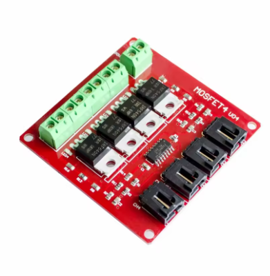
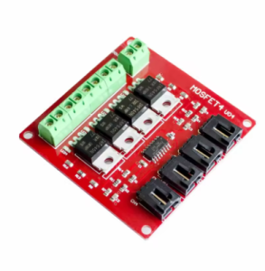
The 4-Channel Isolated MOSFET Power Switch Module is a professional-grade, multi-channel electronic brick designed for sophisticated DC power control applications. Based on four powerful IRF540 N-Channel MOSFETs , this module provides a safe, reliable, and scalable solution for switching multiple high-power DC loads independently from a single microcontroller .
Unlike simple relay modules or single-channel switches, this “electronic brick” integrates four independent switching channels, each featuring high-speed optocoupler isolation between the low-voltage control side (your microcontroller) and the high-power load side . This critical isolation protects your sensitive Arduino, Raspberry Pi, ESP32, or PLC from dangerous voltage spikes, back-EMF, and ground loops that are common when switching motors, solenoids, and high-power lighting .
Each channel utilizes the legendary IRF540 MOSFET—a device renowned for its excellent switching characteristics, low on-resistance, and ability to handle substantial DC power . While rated for extreme conditions up to 100V and 33A , this module is optimized for practical use, providing a robust platform for controlling multiple DC devices simultaneously or creating complex automation sequences.
This module serves as the ideal foundation for projects requiring multi-axis control, such as:
-
Multi-motor robotics and animatronics
-
Intelligent lighting systems with multiple zones
-
Industrial automation and PLC interfacing
-
Sequential timing and process control
-
Multi-valve fluid handling systems
Whether you are building a complex animatronic display, automating a greenhouse irrigation system with multiple valves, or controlling different zones of high-power LED lighting, this 4-channel isolated MOSFET module provides the clean, organized, and protected interface you need .
Key Features
-
Four Independent High-Power Channels: Provides four separate N-Channel MOSFET switches, each capable of independently controlling a different DC load. This allows for complex, multi-device control from a single compact module .
-
IRF540 Power MOSFETs: Each channel is built around the robust IRF540 N-Channel MOSFET, a industry-standard component known for its low on-resistance (RDS(on) ≤ 0.077Ω) and excellent switching characteristics, ensuring efficient power delivery and minimal heat generation .
-
Opto-Isolated Control Inputs: Each of the four control channels is isolated using high-speed optocouplers (typically PS2801-4 or similar). This provides galvanic isolation between your low-voltage microcontroller (3.3V-5V) and the high-power load circuit (up to 100V), protecting your valuable control electronics from electrical noise and potential damage .
-
High Voltage & Current Capability: The module can switch DC loads with voltages up to 100V and handle continuous currents up to 33A per channel under ideal conditions (with proper heatsinking). For practical, continuous use, it is a powerful solution for 12V, 24V, and 48V systems .
-
Superior Solid-State Alternative to Relays: Unlike mechanical relays, this MOSFET module offers silent operation (no clicking), much faster switching speeds (ideal for PWM), and no mechanical contacts to wear out, pit, or weld over time. It can handle extremely short switching times that would destroy a mechanical relay .
-
“Electronic Brick” / Building Block Design: Designed as a modular electronic brick, it features a clear layout with screw terminals for high-power connections and a pin header for control signals, making it easy to integrate into larger systems and stack with other modules .
-
Wide Control Logic Compatibility: The opto-isolated inputs accept a wide range of control voltages (typically 3.3V to 5V), making them directly compatible with a vast array of microcontrollers, single-board computers, and industrial controllers .
-
Visual Status Indicators: Each channel typically features an onboard LED that illuminates when the MOSFET is switched on, providing immediate visual feedback for troubleshooting and monitoring .
-
Versatile DC Applications: Perfect for switching DC motors, solenoids, high-power LEDs, DC pumps, fans, and other DC-powered devices. It can also be used for PWM-based dimming and speed control (with appropriate frequency selection) .
Technical Specifications
Pinout & Interface Guide
The module is clearly divided into a control side (for your microcontroller) and a power side (for your loads).
Control Side (Pin Header)
-
VCC (+5V): Connect to your microcontroller’s 3.3V or 5V output. This powers the optocoupler LEDs and the channel status LEDs .
-
GND (Ground): Common ground for the control side. Connect to a GND pin on your microcontroller.
-
IN1, IN2, IN3, IN4 (Control Inputs): These are the four individual control pins. Apply a HIGH logic signal (3.3V-5V) to the corresponding input to turn that specific MOSFET channel ON. Apply LOW (0V) to turn it OFF . Sending a PWM signal allows for dimming or speed control.
Power Side (Screw Terminals)
-
V+ (or +V): This is the common positive input for all loads. Connect the positive wire from your external DC power supply (e.g., a 12V battery or 24V adapter) to this terminal. This terminal is shared across all four channels .
-
S1, S2, S3, S4 (Switched Outputs): These are the four independent, switched outputs. The MOSFET acts as a switch between this terminal and the power supply ground. To connect a load:
-
Connect the positive (+) wire of your load directly to the positive (+) terminal of your external power supply.
-
Connect the negative (-) wire of your load to the corresponding S terminal (e.g., for load 1, connect to S1).
Important Grounding: While the control and power sides are isolated, the control side GND must be connected to your microcontroller, and the power side GND must be connected to your external power supply’s negative terminal. They are not directly connected on the module, which is the purpose of the isolation .
Usage Guide
Important Safety Warnings
-
DC ONLY: This module is designed for DC circuits only. Never connect AC mains power (e.g., household 110V/220V AC) to this module. It is not suitable for AC control and will be destroyed, posing a serious safety hazard .
-
Inductive Loads: When controlling inductive loads like motors, solenoids, or relays, you MUST add an external flyback (snubber) diode across the load’s terminals (cathode/banded end to load positive, anode to load negative) to protect the MOSFET from voltage spikes . The module does not typically include these diodes.
-
Heatsinking: The IRF540 can theoretically handle up to 33A, but at high currents, it will generate significant heat. For continuous operation above 5A per channel, a heatsink is absolutely required to prevent thermal damage. The module may allow you to bend the MOSFETs up and attach your own heatsinks .
-
Load Voltage: Do not exceed the maximum load voltage of 100V DC on the power side . Applying a higher voltage can permanently damage the MOSFETs.
Wiring Guide (Controlling Multiple 12V Loads with an Arduino)
This example shows how to control two different 12V devices (a motor and an LED strip) using two channels of the module.
Basic Arduino Example Code
This code demonstrates independent on/off control and PWM speed/dimming control on two channels.
int motorPin = 9;
int ledPin = 8;
void setup() {
pinMode(motorPin, OUTPUT);
pinMode(ledPin, OUTPUT);
}
void loop() {
digitalWrite(ledPin, HIGH);
delay(2000);
for (int speed = 0; speed <= 255; speed++) {
analogWrite(motorPin, speed);
delay(10);
}
delay(1000);
digitalWrite(ledPin, LOW);
delay(1000);
analogWrite(motorPin, 0);
delay(2000);
}
Q: What is the main advantage of this isolated module over a non-isolated one?
The key advantage is safety and noise immunity. The opto-isolation creates a complete electrical barrier between your sensitive microcontroller (e.g., Arduino, Raspberry Pi) and the high-power, potentially noisy load circuit . This protects your controller from voltage spikes (back-EMF) generated by motors and solenoids, eliminates ground loops, and ensures stable operation in electrically noisy environments.
Q: What's the difference between this MOSFET module and a relay module?
-
Speed & Control: MOSFETs can switch on and off much faster than relays, enabling Pulse Width Modulation (PWM) for dimming lights or controlling motor speed . Relays are too slow for PWM.
-
Noise & Durability: MOSFETs are solid-state and operate silently, with no moving parts to wear out. Relays produce an audible “click” and have mechanical contacts that can pit, weld, or fail over time, especially with frequent switching .
-
Contact Type: A relay provides a true mechanical contact that can handle both AC and DC. A MOSFET is a semiconductor that can only handle DC in one direction
Q: What types of loads can I control with this module?
You can control various DC loads, including:
-
DC motors and actuators (for speed and direction via PWM)
-
High-power LED strips and lighting (for dimming)
-
Solenoid valves and relays (for fluid control)
-
DC pumps and fans
-
Other DC-powered devices up to 100V
Q: Can this module control AC loads (like a household light or appliance)?
No, absolutely not. This module is strictly for DC circuits only . Attempting to control AC mains voltage with this module is extremely dangerous and will destroy the module instantly.
Q: Can I use this module with a 3.3V logic controller like a Raspberry Pi or ESP32?
Yes. The control inputs are compatible with 3.3V logic levels, making it directly usable with these controllers . Ensure you provide 3.3V to the VCC pin if you want the status LEDs to run at that logic level.
Q: What is the real-world current limit for this module?
While the IRF540 MOSFET itself can handle up to 33A , the practical, continuous current is limited by the module’s PCB traces, the terminal blocks, and the lack of a heatsink. For continuous, reliable operation, it’s wise to stay within 5A to 10A per channel. For short bursts or with a good heatsink attached, you can push higher
Q: Do I need to use an external power supply for the loads?
Yes. The power for your loads (motors, LEDs) must come from an external power supply (e.g., a 12V battery or AC-DC adapter) connected to the module’s V+ terminal and the negative of that supply to the module’s GND. Powering high-current loads from your microcontroller’s 5V pin will damage your microcontroller.
Q: The MOSFETs get hot. Is this normal?
Yes, some heat is normal when switching high currents. The IRF540 has a low on-resistance, but at 5A, it will still dissipate a few watts. If the MOSFETs are too hot to touch, you need better cooling. You can carefully bend them up and attach small heatsinks to the metal tab . If the chip driving the MOSFET gets hot, the load may be too high or the switching frequency (PWM) may be too high.
Q: Can I use PWM for dimming LEDs or controlling motor speed?
Yes. This module is excellent for PWM control. You can send a PWM signal from your microcontroller (e.g., analogWrite() on Arduino) to the input pins to achieve smooth dimming or speed control . You may need to experiment with PWM frequencies to find the best balance between audible noise and smooth performance.
Q: The status LED lights up, but my load doesn't turn on. What's wrong?
This is a common wiring issue with high-side vs. low-side switching. Remember, these N-Channel MOSFETs switch the ground (negative) side of the circuit.
-
Check Load Wiring: Ensure the positive (+) of your load goes directly to the positive (+) of your external power supply.
-
Check Module Wiring: Ensure the negative (-) of your load goes to the S terminal of the corresponding channel.
-
Check Ground: Ensure the GND of your external power supply is connected to the GND terminal on the power side of the module. This completes the circuit through the MOSFET.
-
Check Power: Verify your external power supply is on and outputting the correct voltage.
Q: The load stays on even when the control signal is set to LOW.
This indicates the MOSFET is not fully turning off. The most common cause is that the gate charge is not being drained. Ensure that your microcontroller pin is configured as an OUTPUT and is being driven firmly to LOW (0V) . A failing optocoupler or a shorted MOSFET could also cause this.
Q: Do I need a flyback diode for my motor?
Yes, absolutely. Whenever you switch an inductive load like a DC motor, solenoid, or pump, you must connect a flyback diode (e.g., 1N400x or 1N4148) across the motor’s terminals. Place the diode with the cathode (banded end) connected to the motor’s positive supply and the anode to the motor’s negative. This protects the MOSFET from the high-voltage spike generated when the motor is switched off
Q: My PWM control doesn't work smoothly (jerky motion or flickering light).
This is often a frequency issue. Try lowering the PWM frequency in your code. Different motors and LEDs respond best to different frequencies. Experiment with values from a few hundred Hz to a few kHz.