Product Overview
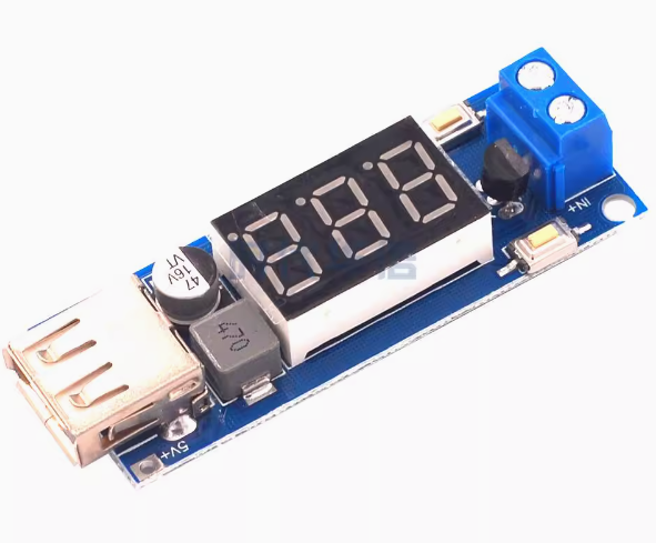
The 6.5-40V to 5V DC-DC Step-Down Power Converter Module is a versatile, high-efficiency switching regulator designed to convert higher DC voltages (from 6.5V to 40V) into a stable 5V output suitable for powering USB devices. This all-in-one module combines a buck converter, a digital LED voltmeter, and a USB charging port in a compact, ready-to-use package.
Whether you need to charge a smartphone from a 12V car battery, power a Raspberry Pi from a 24V industrial supply, or monitor battery voltage on a solar power system, this module provides a simple and efficient solution. With its wide input voltage range, it is compatible with 12V, 24V, and even 36V systems commonly found in vehicles, trucks, boats, and industrial equipment.
A standout feature of this module is its intelligent push-button control. Unlike many converters that output power as soon as they are connected, this module defaults to an “output off” state for safety. You must press the “Output Enable” button to activate the USB port. This prevents unwanted power drain or accidental device activation when the module is first connected. Additionally, a “Low Power” button puts the module into an ultra-low-power standby mode, disabling both the display and the USB output to conserve battery power when not in use.
The integrated LED voltmeter provides real-time monitoring of the input voltage, allowing you to keep an eye on your battery’s state of charge. For precision applications, the voltmeter can also be manually calibrated to ensure accurate readings.
Key Features
-
Wide Input Voltage Range: Accepts DC input from 4.5V to 40V, with a regulated 5V output available when the input is between 6.5V and 40V. Compatible with 12V, 24V, and 36V systems.
-
5V/2A USB Output: Provides a stable 5V output with a maximum current of 2A, suitable for charging smartphones, tablets, MP3 players, and other USB-powered devices.
-
High-Efficiency Conversion: Utilizes a switching regulator design to achieve high efficiency and low ripple, minimizing power loss and heat generation compared to linear regulators.
-
Integrated LED Voltmeter: Features a built-in digital voltmeter that displays the input voltage in real-time, with an automatic calibration function for accuracy.
-
Push-Button Output Control: The “Output Enable” button allows you to turn the USB output on or off as needed, while the “Low Power” button puts the module into standby mode to conserve energy.
-
Comprehensive Protection: Includes reverse polarity protection, over-current protection, and over-temperature protection to safeguard the module and your connected devices.
-
Compact and Lightweight: Small form factor (approx. 58mm × 21mm × 10mm) and lightweight (approx. 13g) allows for easy integration into tight spaces.
-
USB Power Indicator: A convenient LED indicator illuminates when the USB output is enabled, providing clear visual confirmation.
-
Voltmeter Calibration Capability: The voltmeter can be manually calibrated to ensure accurate voltage readings for your specific setup.
Technical Specifications
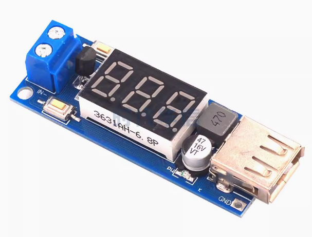
Pinout & Interface Guide
Input Side
-
IN+ (VIN): Connect to the positive terminal of your DC power source (e.g., 12V battery, 24V power supply). Two connection points are available: a terminal block for permanent wiring and a set of pre-soldered wires.
-
IN- (GND): Connect to the negative terminal (ground) of your DC power source.
Output Side
-
USB-A Port: Standard female USB connector for charging or powering USB devices. Output is enabled/disabled via the “Output Enable” button.
-
Solder Pads (5V/GND): Optional output pads for hardwiring a 5V load without using the USB port.
User Controls
-
Output Enable Button: Press to turn the USB output ON. The USB power indicator LED will illuminate.
-
Low Power Button: Press to turn OFF the USB output and disable the LED voltmeter display, entering low-power standby mode.
Status Indicators
Usage Guide
Wiring Instructions
IMPORTANT: Always disconnect the input power source before wiring or modifying connections.
Basic Connection (12V Car Battery)
-
Connect Input: Connect the IN+ wire to the positive terminal of your 12V car battery. Connect the IN- wire to the battery negative terminal (ground).
-
Verify Input Voltage: The LED voltmeter will display the input voltage (e.g., 12.6V for a fully charged battery).
-
Enable Output: Press the “Output Enable” button. The USB power indicator LED will light up, and 5V will be available on the USB port.
-
Connect Device: Plug your USB device into the USB-A port to begin charging.
Using Low Power Mode
To conserve battery power when the USB output is not needed:
-
Press the “Low Power” button.
-
The USB output will shut down, and the LED voltmeter display will turn off.
-
The module will enter an ultra-low-power standby state, drawing minimal current from your battery.
Voltmeter Calibration
For accurate voltage readings, you can calibrate the built-in voltmeter:
-
Power On: Connect the module to a known stable DC power source.
-
Enter Calibration Mode: Press and hold the “Output Enable” button for approximately 2 seconds, then release. The voltmeter display will begin to flash.
-
Adjust Display Value:
-
Exit Calibration Mode: Press and hold the “Output Enable” button for another 2 seconds, then release. The display will stop flashing, and the calibration value will be saved automatically (persists after power loss).
Applications
-
Vehicle Battery Monitor & USB Charger: Monitor your car or motorcycle battery voltage while providing a convenient USB charging port for phones and GPS devices.
-
Raspberry Pi / Arduino Power Supply: Power a 5V single-board computer from a 12V or 24V battery or power supply.
-
Solar Power Systems: Step down voltage from a 12V/24V solar battery bank to power USB devices or 5V electronics.
-
DIY Projects: Provide a regulated 5V supply and voltage monitoring for custom electronics projects.
-
Industrial Control: Power 5V sensors or logic controllers from 24V industrial power rails.
Important Considerations
-
Input Voltage Requirement: While the module can operate down to 4.5V, a stable 5V output is only guaranteed when the input voltage is between 6.5V and 40V.
-
Output Current Limit: The module is rated for a maximum continuous output current of 2A. Exceeding this may trigger over-current protection or cause overheating.
-
Heat Dissipation: Under high load conditions (close to 2A), the module may become warm. Ensure adequate ventilation in the installation location.
-
Reverse Polarity Protection: The module includes reverse polarity protection, which safeguards it if the input wires are accidentally reversed. However, correct wiring should always be observed.
Q: Can I use this module to charge my phone?
Yes. The module provides a standard USB-A port with 5V/2A output, which is suitable for charging most smartphones, tablets, and other USB-powered devices.
Q: Why is the USB output not working when I first connect power?
This is a safety feature of this module. Unlike many converters, the USB output is OFF by default. You must press the “Output Enable” button to activate the USB port.
Q: What is the purpose of the "Low Power" button?
Pressing the “Low Power” button turns off both the USB output and the LED voltmeter display, putting the module into an ultra-low-power standby mode. This is useful for conserving battery power when the charger is not in use.
Q: What does the LED voltmeter display?
The voltmeter displays the input voltage (the voltage of the power source connected to the module), not the output voltage. This allows you to monitor the state of your battery or power supply.
Q: Can I use this module to power a Raspberry Pi?
Yes. The module’s 5V/2A output is well-suited for powering a Raspberry Pi (including the Raspberry Pi 3B+ and 4, though the Pi 4 may require careful power management for heavy loads). Many users have successfully used this module for this purpose.
Q: What is the maximum input voltage for this module?
The module can accept up to 40V DC. For a stable 5V output, the input should be between 6.5V and 40V.
Q: What is the maximum output current?
The module is rated for a maximum continuous output current of 2A. For reliable operation, it is recommended to stay within this limit.
Q: Can I use this module with a 24V truck battery?
Yes. The module’s wide input range (6.5V–40V) makes it perfectly compatible with standard 24V truck electrical systems.
Q: The module gets warm during use. Is this normal?
Some warmth is normal, especially when charging devices near the 2A limit. The module includes over-temperature protection to prevent damage. If it becomes too hot, ensure it is in a well-ventilated area and reduce the load if necessary.
Q: The voltmeter reading seems inaccurate. How can I fix this?
The voltmeter can be manually calibrated using the push buttons. Press and hold the “Output Enable” button for 2 seconds to enter calibration mode, then use the buttons to adjust the displayed value.
Q: Does the module have reverse polarity protection?
Yes. The module includes reverse polarity protection, which will protect it if the input wires are accidentally reversed. However, correct wiring should always be observed.
Q: The USB port is not providing power even though the indicator light is on.
If the USB power indicator is lit but your device is not charging, check:
-
Ensure the connected device’s charging cable is functional.
-
The device may be drawing more than 2A, triggering over-current protection.
-
The input voltage may have dropped below 6.5V.
Q: What happens if I exceed the 2A output limit?
The module includes over-current protection. If the current exceeds the safe limit, the output may shut down to protect the module and your device. Reduce the load and press the “Output Enable” button to reset.