


Description
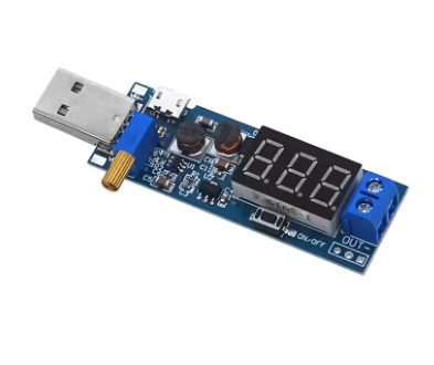
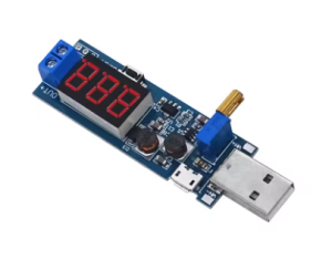
The Adjustable DC-DC USB Boost Converter Module is a compact and highly efficient power solution designed to elevate standard 5V USB voltage to higher, adjustable output levels. Whether you need to power a 12V LED strip from a power bank, run a 9V pedal from a USB port, or create a variable desktop power supply, this tiny module delivers reliable performance in a convenient USB stick form factor.
At the heart of this module is the MT3608 chip – a constant frequency, current mode step-up converter that operates at a high 1.2MHz switching frequency . This advanced design integrates an 80mΩ power MOSFET and supports up to 2A output current, making it ideal for small to medium power applications .
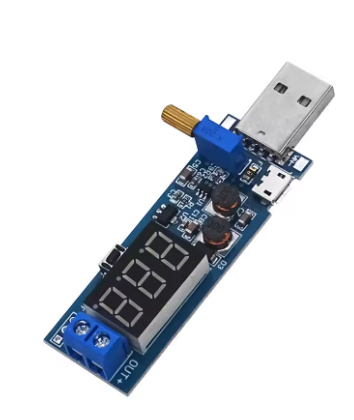
How It Works: As a dedicated “Boost” converter, this module only steps voltage up. It takes a standard 5V USB input and efficiently increases it to a higher, adjustable output voltage ranging from approximately 6V up to 28V . The onboard multi-turn potentiometer allows you to dial in common voltages such as 9V, 12V, 15V, 18V, or 24V with a simple screwdriver turn .
Key Design Benefits:
-
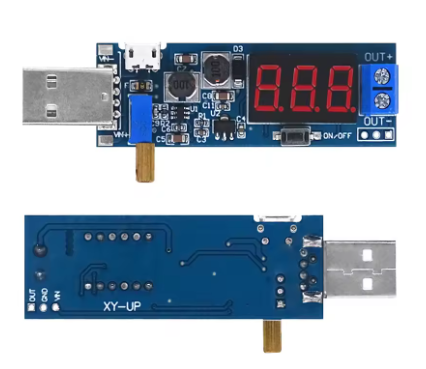
Plug-and-Play Convenience: Built-in Micro USB or USB Type-C input port allows direct connection to any USB charger, power bank, or computer port
-
High Efficiency: Up to 93-97% conversion efficiency minimizes power loss and heat generation
-
Compact Form Factor: Small enough to fit inside most project enclosures or plug directly into a USB port
-
Adjustable Output: Multi-turn potentiometer allows precise voltage setting from ~5V to 28V
Important Operating Note: This is a step-up (boost) converter only. The output voltage must be set higher than the input voltage (typically at least 2V higher). It cannot step down voltage – for example, you cannot use it to convert 12V to 5V .
Whether you are a hobbyist powering portable electronics, an IoT developer needing a 12V rail from a USB power bank, or a professional creating a custom bench power supply, this USB boost converter module provides a simple, reliable, and low-cost solution for all your voltage boosting needs.
Key Features
-
5V USB Input – Built-in USB connector (Micro USB or Type-C) allows direct connection to any USB charger, power bank, or computer port
-
Adjustable Output Voltage – Output can be set from approximately 5V up to 28V via onboard multi-turn potentiometer (common settings: 9V, 12V, 15V, 18V, 24V)
-
2A Maximum Output Current – Supports up to 2A peak output current (1A recommended for continuous use)
-
High Conversion Efficiency – Up to 93-97% efficiency minimizes power loss and heat generation
-
1.2MHz Switching Frequency – High-frequency operation allows for small components and low output ripple
-
Wide Compatibility – Powers 3.3V, 5V, 9V, 12V, 15V, 18V, and 24V devices from a single 5V USB source
-
Integrated Power MOSFET – Built-in 80mΩ, 4A switch handles high current efficiently
-
Small Form Factor – Compact dimensions (approx. 30-36mm × 17mm) ideal for portable projects
-
Built-in Protection – Features over-current limiting and thermal overload protection
-
LED Indicator – Power indicator LED shows when module is active
Technical Parameters
| Parameter | Value |
|---|---|
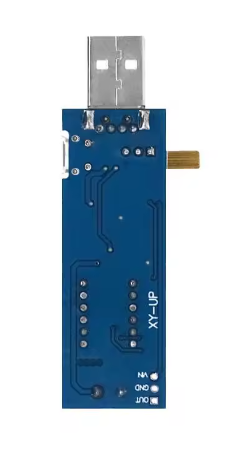
| Input Voltage | 5V DC (via USB) or 2V – 24V (via solder pads) |
| Output Voltage Range | Adjustable 3V – 28V (set via potentiometer) |
| Maximum Output Current | 2A (peak) / 1A (recommended continuous) |
| Conversion Efficiency | Up to 93-97% |
| Switching Frequency | 1.2 MHz |
| Output Ripple | < 50mV (typical) |
| Operating Temperature | -40°C to +85°C |
| Module Dimensions | 30 × 17 × 14 mm (approx.) |
| Weight | ~7g |
