Product Overview
The CP2102 USB to TTL Serial Converter is a compact, high-performance communication adapter designed to bridge the gap between your computer’s USB port and your microcontroller or embedded systems. This pink-colored 4-pin module provides a simple, reliable solution for programming, debugging, and serial communication with devices such as Arduino boards, STM32, ESP8266, ESP32, and Raspberry Pi .
At its core is the Silicon Labs CP2102 chip, an industrial-grade USB-to-UART bridge controller known for its excellent stability, high performance, and broad driver support across Windows, macOS, and Linux operating systems . The module supports both 3.3V and 5V logic levels, making it versatile for a wide range of microcontroller projects .
The compact design (approximately 24mm × 15mm) occupies minimal space, while the onboard 500mA self-recovery fuse protects your computer’s USB port and the module itself from accidental short circuits . Built-in TX/RX status LEDs provide real-time visual feedback of data transmission activity, simplifying debugging and troubleshooting .
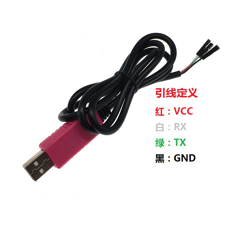
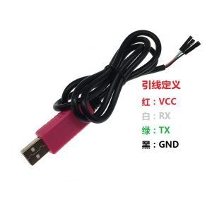
This 4-pin version features a standard pinout with power supply outputs (5V and 3.3V), transmit (TXD), receive (RXD), and ground (GND). The module is fully compatible with Windows 10 (and newer versions like Windows 11), as well as macOS and Linux systems .
Key Features
-
Industrial-grade CP2102 Chipset: Powered by Silicon Labs CP2102 USB-to-UART bridge controller, offering high stability and reliable data transfer
-
Dual Voltage Compatibility: Supports both 3.3V and 5V logic levels, making it suitable for a wide range of microcontroller projects
-
Compact and Portable Size: Ultra-small PCB design (approx. 24mm × 15mm) fits easily in your toolkit
-
500mA Self-Recovery Fuse: Onboard resettable fuse protects your computer and module from short circuits; recovers automatically after fault clearance
-
Built-in TX/RX Status LEDs: Visual indicators for data transmission and reception – transmit data lights up when sending; receive data lights up when receiving
-
High-Speed Communication: Supports baud rates from 300 bps up to 1 Mbps, suitable for fast firmware uploads and real-time data logging
-
Wide Operating System Support: Compatible with Windows (7, 8, 10, 11), macOS, and Linux
-
Plug-and-Play Installation: Simple driver installation process with Silicon Labs VCP drivers
Technical Specifications
Pinout & Interface Guide
Important: The TXD pin of the module should connect to the RXD pin of your target device, and the RXD pin of the module should connect to the TXD pin of your target device.
Usage Guide
Driver Installation
The CP2102 requires Virtual COM Port (VCP) drivers. Download the latest “CP210x Universal Windows Driver” from the Silicon Labs website :
Steps:
-
Run the driver installer as Administrator
-
Follow the installation wizard prompts
-
Connect the module to your computer via USB
-
Check Device Manager → Ports (COM & LPT) for “Silicon Labs CP210x USB to UART Bridge”
Troubleshooting: If the device does not appear, try a different USB port or reinstall the driver. Windows 10/11 users may need to temporarily disable Driver Signature Enforcement for initial installation .
Changing COM Port Number
If the assigned COM port number conflicts with existing devices:
-
Open Device Manager → Ports (COM & LPT)
-
Right-click “Silicon Labs CP210x USB to UART Bridge”
-
Select Properties → Port Settings → Advanced
-
Choose a new COM port number from the dropdown list
Loopback Test (Functional Test)
To verify the module is working correctly :
-
Connect the TXD and RXD pins together using a jumper wire
-
Open a serial terminal program (e.g., Putty, Arduino Serial Monitor)
-
Select the module’s COM port and set baud rate to 115200
-
Type characters – they should be echoed back to the terminal
-
This confirms both transmit and receive paths are functional
Common Applications
STC Microcontroller Programming Tips
This module is commonly used for STC microcontroller development . Follow the “cold start” procedure:
-
Disconnect power from the target board
-
Click Download in STC-ISP software
-
Reconnect power to the target board within 2 seconds
-
Wait for “Operation Success” message
Power Supply Considerations
-
The 5V pin can supply up to 500mA – sufficient for low-power microcontrollers
-
The 3.3V pin provides regulated 3.3V output up to 100mA
-
For power-hungry devices (motors, servos, high-power LEDs), use a separate external power supply
Q: What is the difference between CP2102 and CH340/PL2303?
The CP2102 from Silicon Labs is widely recognized for superior stability and driver reliability compared to CH340 and older PL2303 chips . It is the industrial-grade choice for professional applications .
Q: Does this module support Windows 11?
Yes. The CP2102 is fully compatible with Windows 11, with native driver support for modern operating systems .
Q: Can this module power my microcontroller project?
Yes, with limitations. The 5V output can provide up to 500mA, sufficient for microcontrollers like Arduino Pro Mini, ESP8266, and STM32. For projects requiring higher current (motors, servos), use external power .
Q: What is the maximum baud rate supported?
The CP2102 supports baud rates from 300 bps up to 1 Mbps (1,000,000 bps) , suitable for high-speed data transmission and fast firmware uploads .
Q: Is this module compatible with Raspberry Pi?
Yes. The CP2102 is recognized on Raspberry Pi systems. Use it for serial console access or to interface with UART devices .
Q: Why isn't my computer recognizing the device?
Follow this checklist:
-
Ensure CP2102 drivers are properly installed from Silicon Labs website
-
Try a different USB port or USB cable
-
Check Device Manager for yellow warning indicators
-
On Windows, check if Driver Signature Enforcement is blocking installation
Q: How do I perform a self-test to verify the module is working?
Perform a loopback test by connecting TXD and RXD pins together . Open a serial terminal and type characters – they should echo back, confirming both transmit and receive paths function correctly.
Q: The TX/RX LEDs are not blinking. Is something wrong?
The LEDs blink only during data communication. At lower baud rates, they blink slower; at high baud rates (e.g., 115200+), they may appear dim or solid due to the rapid flashing. If no data is being transmitted, the LEDs remain off.
Q: Can I use this module for Arduino programming?
Yes, but with manual reset. This 4-pin version lacks a DTR signal line. You will need to manually reset your Arduino board when uploading sketches. Press the reset button just as the upload begins .
Q: What can I build with this CP2102 module?
Popular applications include :
-
Microcontroller programming: STC series, ESP8266, ESP32, STM32
-
Raspberry Pi console access: Debugging without a monitor
-
Router/switch firmware recovery: OpenWrt, DD-WRT installation
-
GPS module interfacing: Reading GPS data on computer
-
Industrial equipment communication: TTL serial port access
-
Serial debugging: Real-time log monitoring from any UART device
Q: Is this module compatible with 5V logic devices?
Yes. The CP2102’s I/O pins are 3.3V logic, but are 5V tolerant . Many 5V devices recognize 3.3V as logic HIGH.
Q: Does the module have overcurrent protection?
Yes. The onboard 500mA self-recovery resettable fuse protects against short circuits and overcurrent . If a short occurs, the fuse automatically disconnects and recovers once the fault is cleared.
Q: Can I change the assigned COM port number?
Yes. In Device Manager, right-click the device → Properties → Port Settings → Advanced → select a new COM port number from the dropdown list .