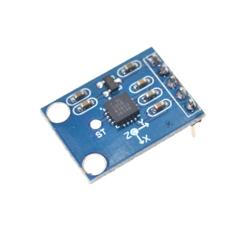
Product Overview
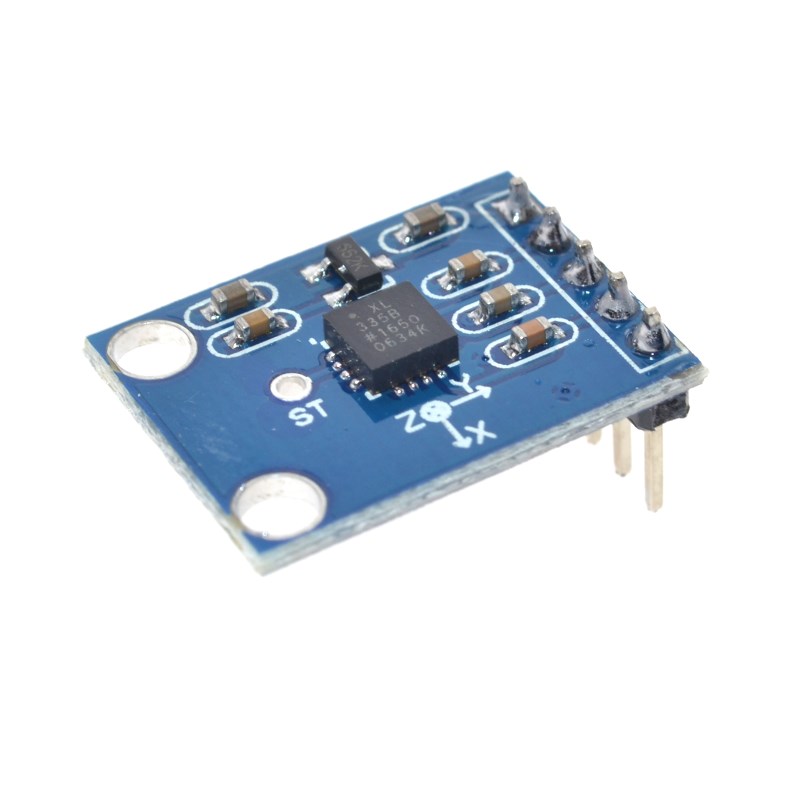
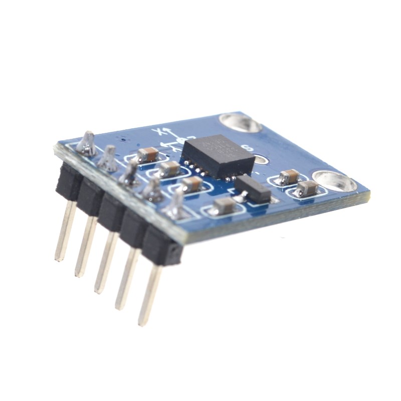
The GY-61 ADXL335 3-axis Accelerometer Module is a complete, low-power, analog output accelerometer designed for precise measurement of acceleration, tilt, and vibration across three axes (X, Y, and Z). Based on the industry-standard Analog Devices ADXL335 MEMS accelerometer, this module provides simple, noise-free analog voltage outputs that are directly proportional to the acceleration experienced on each axis .
The ADXL335 measures acceleration with a selectable full-scale range of ±3g (minimum) . It can measure both static acceleration—the constant force of gravity used for tilt sensing—and dynamic acceleration caused by motion, shock, or vibration . The output signals are analog voltages with a typical sensitivity of 300 mV/g (at 3V supply).
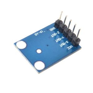
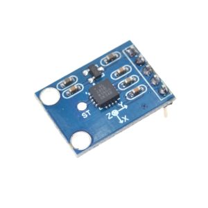
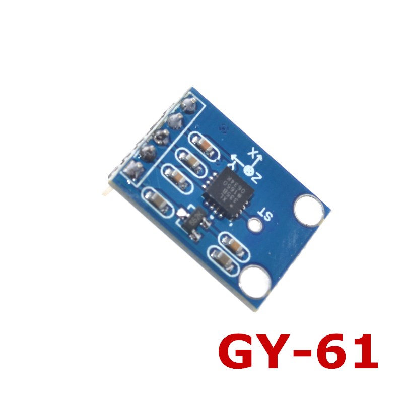
The GY-61 module breaks out all the essential pins onto a compact, easy-to-use board. Crucially, it often includes an onboard 3.3V voltage regulator, allowing you to power it directly from a 5V supply (like an Arduino) while ensuring the ADXL335 chip receives the correct 3.3V operating voltage . The analog outputs are ratiometric, meaning the output voltage scales proportionally with the supply voltage. This characteristic makes interfacing with microcontrollers straightforward, as the 0g offset point remains at VCC/2 regardless of the supply voltage .
Whether you need to measure the tilt of a robotic arm, detect the orientation of a handheld game controller, log vehicle vibration, or simply determine which way is “up” in your DIY project, this module offers a reliable, cost-effective solution with no complex programming or digital communication protocols to manage .
Key Features
-
3-Axis Sensing: Measures acceleration simultaneously on X, Y, and Z axes, providing complete orientation information .
-
±3g Measurement Range: Full-scale range of at least ±3g, suitable for tilt sensing and moderate motion detection .
-
Analog Voltage Output: Simple, noise-free analog outputs eliminate the need for complex digital libraries .
-
High Sensitivity: Typical sensitivity of 300 mV/g (at 3V supply), providing good resolution for tilt detection .
-
Low Power Consumption: Operates on just 350 µA (typical) , making it ideal for battery-powered applications .
-
Signal-Conditioned Outputs: On-chip signal conditioning provides stable, low-impedance outputs ready for direct connection to a microcontroller’s ADC .
-
Selectable Bandwidth: User-selectable bandwidth via external capacitors (X,Y axes: up to 1600 Hz, Z axis: up to 550 Hz) for noise reduction .
-
Ratiometric Outputs: Output voltage scales proportionally with supply voltage, simplifying ADC interfacing .
-
Onboard 3.3V Regulator: Most GY-61 boards include a voltage regulator, allowing 5V power input while supplying 3.3V to the sensor chip .
-
Ultra-Compact Package: Small module size (approx. 4mm × 4mm × 1.45mm chip on breakout board) fits easily into portable and space-constrained projects .
Technical Specifications
Pinout & Interface Guide
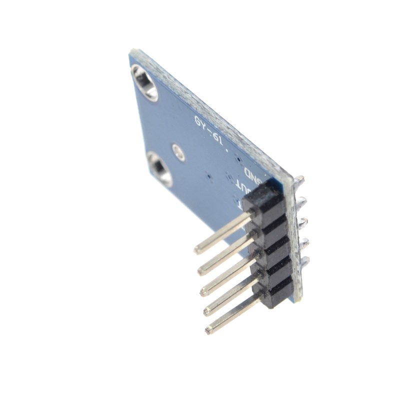
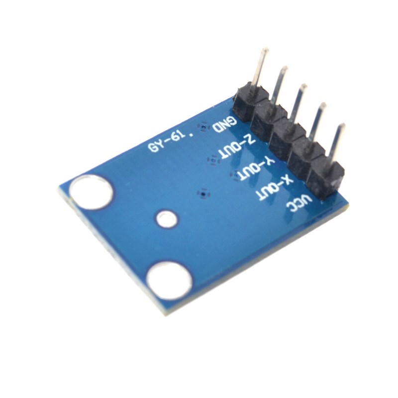
The GY-61 module features a simple 5-pin interface, clearly labeled on the PCB.
Pin Definitions
Wiring Diagram (Arduino Uno)
GY-61 Module          →    Arduino Uno
─────────────────────────────────────────
VCC                   →    5V
GND                   →    GND
X_OUT                 →    A0 (Analog 0)
Y_OUT                 →    A1 (Analog 1)
Z_OUT                 →    A2 (Analog 2)
Important Notes:
-
The module’s analog outputs range from 0V to VCC (the supply voltage applied to VCC pin)
-
For 3.3V microcontrollers (ESP32, ESP8266), connect VCC to 3.3V and adjust ADC reference accordingly
-
The onboard regulator on most GY-61 boards converts 5V to 3.3V for the sensor chip
Theory of Operation
How an Accelerometer Works
The ADXL335 uses MEMS (Micro-Electro-Mechanical Systems) technology. Inside the chip, a tiny polysilicon spring-mass structure deflects under acceleration. Capacitive sensors measure this deflection, and on-chip circuitry converts the capacitance change into an analog voltage proportional to acceleration .
Ratiometric Output Explained
The ADXL335’s output is ratiometric, meaning the output voltage scales proportionally with the supply voltage. Key values are ratiometric:
-
0g Voltage = VCC / 2 (e.g., 1.65V at 3.3V supply)
-
Sensitivity = scales with VCC (e.g., 300 mV/g at 3V, 330 mV/g at 3.3V)
This is convenient because when you power the module from your microcontroller’s VCC pin, the ADC reference and sensor output scale together, minimizing errors .
Voltage-to-Acceleration Formula
To convert an analog reading to acceleration in g-forces, use this formula:
a(g) = (V_OUT – V_0g) / Sensitivity
Where:
-
V_OUT = measured analog voltage at the output pin
-
V_0g = 0g bias voltage (typically VCC/2, e.g., 1.65V at 3.3V supply)
-
Sensitivity = sensor sensitivity (e.g., 0.33 V/g at 3.3V supply)
ADC Value to Acceleration (Arduino)
On a 5V Arduino with 10-bit ADC (0-1023 values):
Steps to convert ADC reading to g-force:
-
Read ADC value: adcValue = analogRead(pin)
-
Convert to voltage: voltage = adcValue × (5.0 / 1023.0)
-
Convert to g-force: gForce = (voltage - 2.5) / 0.33
*Note: At 5V supply, 0g = 2.5V, sensitivity = 330 mV/g (0.33 V/g)*
Usage Guide
Determining Sensor Orientation (In Tilt Applications)
At rest, the accelerometer measures only the static acceleration of gravity (1g). By comparing the outputs on each axis, you can determine the orientation of the module:
Calculating Tilt Angles (Pitch and Roll)
Using the three axes, you can calculate tilt angles. For a sensor mounted flat:
float pitch = atan2(-accelX, sqrt(accelY * accelY + accelZ * accelZ)) * 180 / PI;
float roll = atan2(accelY, accelZ) * 180 / PI;
Selecting Bandwidth with Capacitors
The ADXL335 allows you to set the output bandwidth by adding capacitors to the X_OUT, Y_OUT, and Z_OUT pins. The bandwidth determines the frequency range of acceleration signals that will be faithfully reproduced. Lower bandwidth reduces noise but also reduces the ability to detect fast transients. For most tilt sensing applications (static or low-frequency motion), the onboard default capacitors are sufficient .
Measuring Dynamic Acceleration (Vibration, Shock)
For applications requiring measurement of fast events (e.g., detecting a bump, measuring vibration), you may need to minimize filtering to capture high-frequency components. Important: The ADXL335’s maximum measurement range is ±3g ( ±3.6g absolute max) . It cannot measure very high-g events like crossbow shots or hard impacts, which may exceed 50g .
Using with Different Microcontrollers
Arduino (5V logic) :
-
Connect VCC to 5V (onboard regulator provides 3.3V to sensor)
-
Analog outputs range from 0V to 5V
-
0g = ~2.5V, ±3g corresponds to approximately 0.5V to 4.5V range
ESP32 / ESP8266 (3.3V logic) :
-
Connect VCC to 3.3V (bypasses onboard regulator; sensor runs directly at 3.3V)
-
Analog outputs range from 0V to 3.3V
-
0g = ~1.65V, ±3g corresponds to approximately 0.33V to 2.97V range
Q: What is the difference between the ADXL335 and digital accelerometers like the MPU6050?
The ADXL335 provides analog voltage outputs, which are simple to read with any microcontroller’s ADC. Digital accelerometers (like the MPU6050) communicate via I2C or SPI, requiring more complex code but offering additional features like built-in gyroscopes and digital signal processing . The ADXL335 is simpler for basic tilt sensing.
Q: Can I power the GY-61 module directly from an Arduino's 5V pin?
Yes. Most GY-61 modules include an onboard 3.3V voltage regulator, allowing you to safely connect VCC to 5V . The sensor chip receives 3.3V from the regulator, while the analog outputs still swing from 0V to 5V (since they are connected to the 5V supply). This is convenient for 5V Arduino boards.
Q: Why do I get non-zero readings on all axes when the module is stationary?
At rest, the sensor still measures the constant force of gravity (1g). Unless the module is perfectly vertical, gravity will have components on multiple axes. Additionally, the 0g bias voltage may not be exactly VCC/2, requiring calibration (subtract the “zero” reading from your measurements) .
Q: The measured voltage at 0g is not exactly VCC/2. Is my sensor faulty?
No, this is normal. The datasheet specifies a 0g bias tolerance of ±50mV (at 3V) . Small variations from the ideal VCC/2 voltage are expected. For best accuracy, measure the actual 0g voltage when the sensor is level and use that value in your calculations.
Q: Can the ADXL335 be used to measure very high-g events like airbag deployment or crossbow shots?
No. The ADXL335 has a measurement range of at least ±3g (±3.6g max) . High-g events like airbag deployment (~100g) or crossbow recoil (~200g) far exceed its range and will saturate the sensor, possibly damaging it . For high-g applications, use a specialized high-g accelerometer (e.g., ADXL377, ±200g).
Q: What is the effect of changing the analog reference voltage (AREF)?
For best accuracy, the ADC reference voltage should match the sensor’s output range. If you power the sensor from 5V and use a 5V Arduino, the default analog reference is VCC (5V), which works well. If you use an external AREF, ensure it is stable and matches the sensor’s output characteristics.
Q: Why are my readings noisy?
Noise can be reduced by:
-
Adding a small capacitor (0.1µF) between each analog output pin and GND (bandwidth limiting)
-
Taking multiple readings and averaging them (smoothValue = (value + oldValue) / 2)
-
Ensuring stable power supply and keeping signal wires short
Q: What is the typical application for this sensor?
Common applications include:
-
Tilt sensing for robotics, self-balancing platforms, and game controllers
-
Orientation detection for screen rotation in portable devices
-
Vibration monitoring in machinery and vehicles (within ±3g range)
-
Motion detection for security systems and activity tracking
-
Angle measurement for solar trackers and antenna positioners
Q: Can I use this module with a 3.3V microcontroller like ESP32 or Raspberry Pi Pico?
Yes. Connect VCC to 3.3V and GND to GND. The analog outputs will range from 0V to 3.3V, matching the ADC input range of these microcontrollers . The 0g output will be approximately 1.65V (3.3V/2). Adjust your voltage calculations accordingly (using 3.3V instead of 5V) .
Q: How do I calibrate the sensor for more accurate readings?
Calibrate by placing the sensor in known orientations (flat, 90° tilt) and recording the output. For each axis, measure the output at 0g (sensor level, axis perpendicular to gravity) and at ±1g (axis aligned with gravity). Use these measured values to create a custom scale factor and offset formula for your specific sensor .