Product Overview
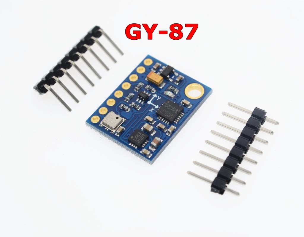
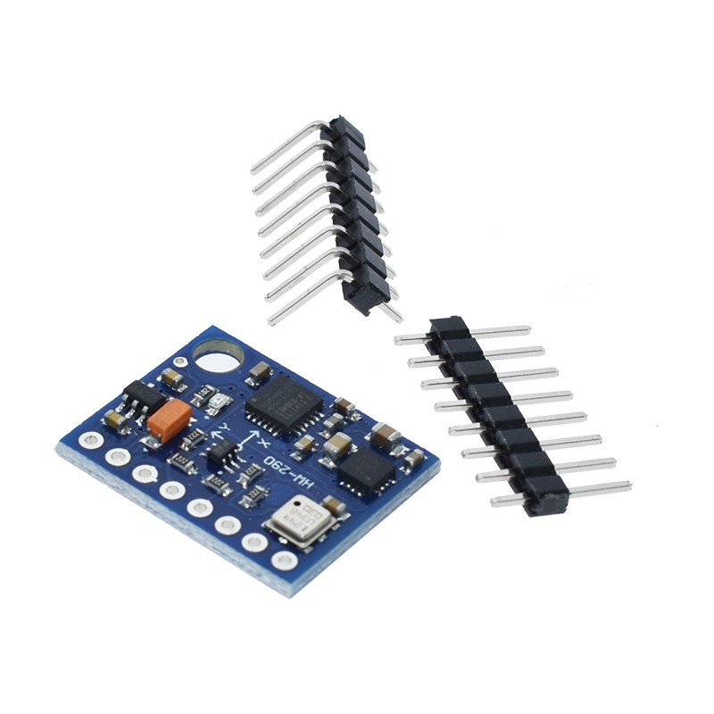
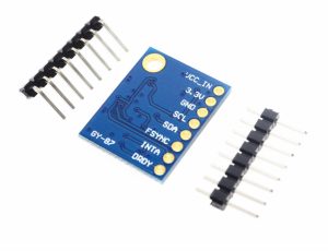
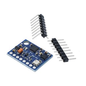
The GY-87 10DOF Sensor Module is a complete motion-tracking solution that integrates three advanced MEMS sensors onto a single compact board: the MPU6050 (3-axis gyroscope + 3-axis accelerometer), the HMC5883L (3-axis magnetometer), and the BMP180 (barometric pressure/temperature sensor) .
This 10-degree-of-freedom (10DOF) module provides a comprehensive set of motion and environmental data—angular velocity, linear acceleration, magnetic heading, atmospheric pressure, and temperature—all accessible through a single I2C interface . The MPU6050 acts as the I2C master for the HMC5883L, which is connected to its auxiliary bus. To access the magnetometer, you must enable I2C bypass mode on the MPU6050, a key configuration step that is detailed in the usage guide below .
The GY-87 is widely used in drone flight controllers (including MWC/MultiWii Copter systems), robotics, GPS navigation systems, head-tracking devices, and weather stations . It is compatible with 3–5V systems and includes onboard logic-level conversion, making it safe for both 3.3V (ESP32, Raspberry Pi) and 5V (Arduino) microcontrollers .
Key Features
-
10 Degrees of Freedom (10DOF): Combines 3-axis gyroscope, 3-axis accelerometer, 3-axis magnetometer, and barometric pressure sensor on one board .
-
MPU6050 – 6‑Axis MotionTracking: Integrated 3‑axis gyroscope and 3‑axis accelerometer with onboard Digital Motion Processor (DMP) . User‑programmable ranges: gyro ±250/500/1000/2000°/s, accel ±2/4/8/16g .
-
HMC5883L – 3‑Axis Digital Compass: 12‑bit ADC with ±8 Gauss range for magnetic heading measurement . Note: The MPU6050 must be configured into I2C bypass mode to access this sensor .
-
BMP180 – Barometric Pressure & Temperature Sensor: High‑resolution pressure measurement for altitude tracking, with a range of 300–1100 hPa .
-
Single I2C Interface: All sensors share the same I2C bus; only two pins (SDA, SCL) are needed to read all data .
-
Wide Voltage Compatibility: Operates on 3–5V DC with onboard logic-level converter (LLC), compatible with both 3.3V and 5V microcontrollers .
-
Onboard Noise Reduction: Built‑in filters reduce interference from motors and other high‑current electronics .
-
Compact Dimensions: Approx. 20 mm × 16 mm to 22 mm × 17 mm, ideal for space‑constrained projects .
-
Power & Interrupt Indicators: Onboard power LED, plus INTA (MPU6050 interrupt) and DRDY (HMC5883L data ready) pins for advanced applications .
Technical Specifications
Pinout & Connection Guide
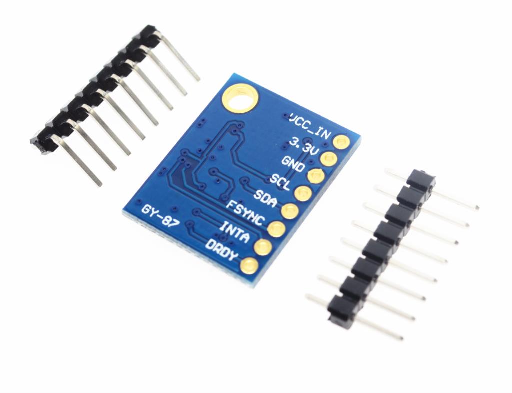
The GY-87 module features an 8-pin configuration. Pin labeling may vary slightly between manufacturers; always verify the silkscreen on your specific board .
Wiring Diagram (Arduino Uno)
GY-87 Module          →    Arduino Uno
─────────────────────────────────────────
VCC_IN (5V)           →    5V
GND                   →    GND
SCL                   →    A5 (SCL)
SDA                   →    A4 (SDA)
I2C Pin Mapping for Common Development Boards
Usage Guide
⚠️ CRITICAL: Enabling I2C Bypass Mode to Read the Magnetometer
The HMC5883L magnetometer is connected to the auxiliary I2C bus of the MPU6050, not directly to the main I2C bus. To access it, you must configure the MPU6050 into I2C bypass mode before initializing the magnetometer .
Without enabling bypass mode, your microcontroller will detect the MPU6050 and BMP180, but will not detect the HMC5883L compass . This is the most common issue when working with the GY-87 module.
Software Setup (Arduino IDE)
Step 1: Install Required Libraries
Install the following libraries via Arduino Library Manager:
-
“Adafruit MPU6050” (installs dependencies: Adafruit Unified Sensor, Adafruit BusIO)
-
“Adafruit BMP085 Library” (for BMP180 sensor)
-
“QMC5883LCompass” or “Adafruit HMC5883L Unified” (for magnetometer)
Step 2: I2C Bypass Mode Configuration – Essential for Magnetometer Access
The following code demonstrates the correct way to initialize the MPU6050 in I2C bypass mode, allowing access to the HMC5883L magnetometer:
GY-87 10DOF Module – Complete Sensor Initialization with I2C Bypass
*/
#include <Wire.h>
#include <Adafruit_Sensor.h>
#include <Adafruit_MPU6050.h>
#include <Adafruit_HMC5883_U.h>
#include <Adafruit_BMP085.h>
Adafruit_MPU6050 mpu;
Adafruit_HMC5883_Unified mag = Adafruit_HMC5883_Unified(12345);
Adafruit_BMP085 bmp;
void setup() {
Serial.begin(115200);
Wire.begin();
if (!mpu.begin()) {
Serial.println("Failed to find MPU6050 chip");
while (1);
}
Serial.println("MPU6050 Found!");
mpu.setI2CBypassEnabled(true);
if (!mag.begin()) {
Serial.println("HMC5883L not found! Check I2C bypass configuration.");
while (1);
}
Serial.println("HMC5883L Found!");
if (!bmp.begin()) {
Serial.println("BMP180 not found!");
while (1);
}
Serial.println("BMP180 Found!");
Serial.println("GY-87 All Sensors Ready");
Serial.println("-----------------------------");
}
void loop() {
sensors_event_t a, g, temp;
mpu.getEvent(&a, &g, &temp);
sensors_event_t magEvent;
mag.getEvent(&magEvent);
float heading = atan2(magEvent.magnetic.y, magEvent.magnetic.x);
if (heading < 0) heading += 2 * PI;
heading = heading * 180 / PI;
float temperature = bmp.readTemperature();
float pressure = bmp.readPressure() / 100.0;
float altitude = bmp.readAltitude();
Serial.print("Accel (m/s²): ");
Serial.print(a.acceleration.x); Serial.print(", ");
Serial.print(a.acceleration.y); Serial.print(", ");
Serial.println(a.acceleration.z);
Serial.print("Gyro (°/s): ");
Serial.print(g.gyro.x); Serial.print(", ");
Serial.print(g.gyro.y); Serial.print(", ");
Serial.println(g.gyro.z);
Serial.print("Heading: ");
Serial.println(heading);
Serial.print("Pressure: ");
Serial.print(pressure);
Serial.println(" hPa");
Serial.print("Altitude: ");
Serial.print(altitude);
Serial.println(" m");
Serial.println("-----------------------------");
delay(500);
}
Step 3: Alternative – Using I2Cdevlib (Manual Register Control)
For more advanced control, you can use the I2Cdevlib libraries :
#include <Wire.h>
#include "I2Cdev.h"
#include "MPU6050.h"
#include "HMC5883L.h"
MPU6050 mpu;
HMC5883L mag;
void setup() {
Wire.begin();
Serial.begin(115200);
mpu.initialize();
mpu.setI2CMasterModeEnabled(false);
mpu.setI2CBypassEnabled(true);
mpu.setSleepEnabled(false);
mag.initialize();
Serial.println(mag.testConnection() ? "HMC5883L OK" : "HMC5883L ERROR");
}
Troubleshooting Common Issues
Issue 1: HMC5883L Not Detected
Symptoms: I2C scanner detects MPU6050 (0x68) and BMP180 (0x77), but not HMC5883L (0x1E).
Solution: This confirms that I2C bypass mode is not enabled on the MPU6050. Add the following lines after initializing the MPU6050 :
mpu.setI2CMasterModeEnabled(false);
mpu.setI2CBypassEnabled(true);
mpu.setSleepEnabled(false);
Issue 2: Magnetometer Heading Inaccurate
Solution: The HMC5883L requires calibration to compensate for hard‑iron offsets from nearby magnetic interference (motors, wires, batteries) . Perform a figure‑eight calibration routine or use the mag.setMagCalibration() function available in some libraries.
Issue 3: QMC5883L vs HMC5883L
Note: Some GY-87 modules ship with a QMC5883L magnetometer instead of the HMC5883L . The QMC5883L has a different I2C address (0x0D) and requires different libraries . If your compass is not responding, try the QMC5883LCompass library and I2C address 0x0D.
Q: Why is my HMC5883L magnetometer not detected?
The HMC5883L is connected to the auxiliary I2C bus of the MPU6050. You must enable I2C bypass mode on the MPU6050 by calling mpu.setI2CBypassEnabled(true); before initializing the magnetometer .
Q: What are the I2C addresses for the sensors?
MPU6050: 0x68 (can be changed to 0x69 via solder jumper), HMC5883L: 0x1E, BMP180: 0x77
Q: Can I use the GY-87 with a 5V Arduino Uno?
Yes. The module includes onboard logic‑level conversion, making it compatible with both 3.3V and 5V systems. Connect VCC_IN to 5V .
Q: Can I use the GY-87 with ESP32 or ESP8266?
Yes. Connect VCC to 3.3V (or use the 3V pin) and SDA/SCL to the appropriate I2C pins. The I2C bypass mode must still be enabled .
Q: Do I need to calibrate the magnetometer?
Yes. For accurate heading, the magnetometer must be calibrated to compensate for hard‑iron offsets from nearby magnetic interference (motors, wires, batteries) .
Q: How do I calculate the heading from magnetometer data?
Use the formula: heading = atan2(my, mx) * 180 / PI. Add 360° if the result is negative .
Q: What are the gyroscope and accelerometer ranges?
MPU6050 gyroscope ranges: ±250, ±500, ±1000, ±2000 °/s; accelerometer ranges: ±2g, ±4g, ±8g, ±16g .
Q: What is the altitude measurement range of the BMP180?
The BMP180 measures pressure from 300 to 1100 hPa, corresponding to altitudes from approximately –500 meters to +9,000 meters .
Q: Can the GY-87 be used for drone flight control?
Yes. The GY-87 is designed for MWC (MultiWii Copter) flight controllers and is commonly used in DIY drone projects .