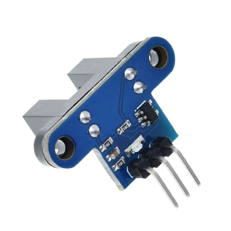
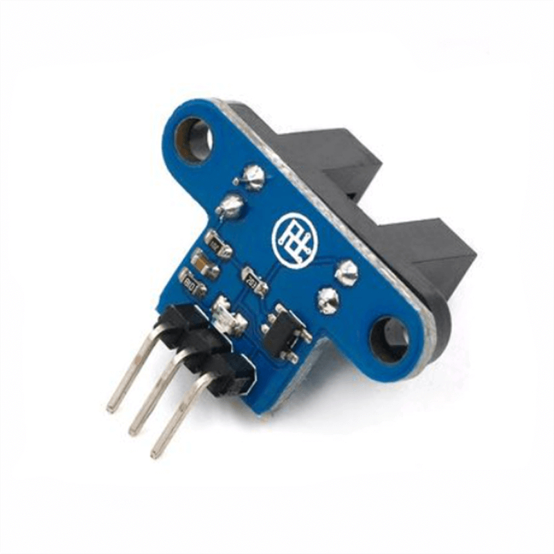
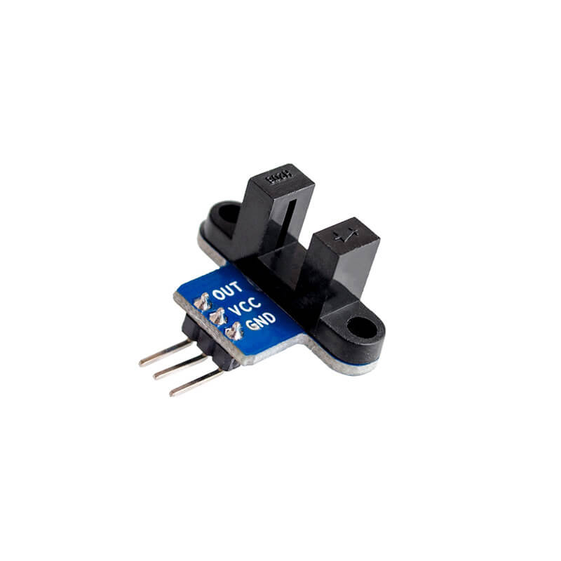
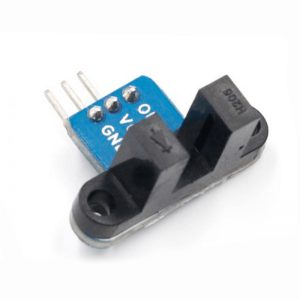
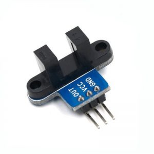
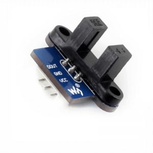
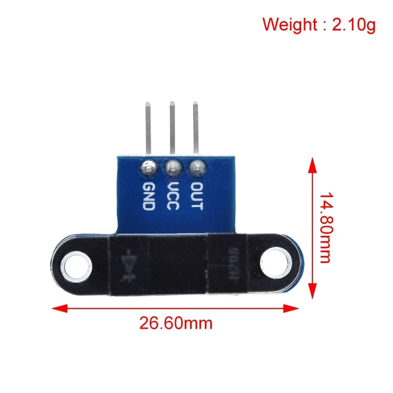
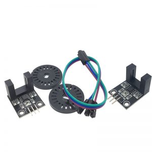
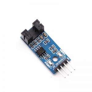
When VCC and GND are connected, the module signal indicator will be on. When there is no block in the module slot, the receiving tube is turned on, and the module OUT outputs high level. When blocking, the OUT output is low and the signal indicator is off. The module OUT can be connected to the relay to form a limit switch and other functions, and can also be connected to the active buzzer module to form an alarm. The OUT output interface can be directly connected to the IO port of the MCU. Generally, it is connected to an external interrupt to detect whether the sensor has a occlusion. For example, the motor code wheel can detect the motor speed.
Programming:
The OUT port of the speed measuring module is linked to the external interrupt port of the MCU. Whenever there is infrared ray conduction, it is an external buffer.
Logic Design:
Measuring distance:
The speed sensor output is a pulse signal, one pulse is interrupted once; the infrared ray is low when it is turned on, so we set the interrupt to the low level touch mode. There are integer grids on the general code wheel. No matter how many grids are in principle, for example, 10 grids, that is, there are 10 spaces. After the motor rotates, the ray is turned on 10 times, and the external low level is 10 times. Install the above ideas, our speed sensor can play the effect, we know that there are 10 interruptions in a circle, so we calculate the number of interruptions, the total number of times obtained is divided by 10 is the number of motor rotation, and then according to the wheel The perimeter, calculating how long the wheel is, you can figure out how far the car has run.
Measuring speed:
According to the idea of measuring distance, we use an MCU timer to calculate how many external interrupts are received in one second. For example, if we receive 20 external interrupts in one second, we can judge that the speed of the car is 1 second and the small wheel rotates two times. Then Then calculate the circumference of the small wheel, you can know the speed of the car for 1 second.
Precautions:
Correct wiring! Do not reverse the positive and negative, so that the board electronics burn out. Arduino players should set the MCU’s I/O port to input mode/receive mode, otherwise they will not be available. Other MCUs, or more advanced control boards such as ARM, must be set to input mode/receive mode if the I/O port needs to be set to input/output mode, otherwise it cannot be used. The 51 series MCU can be used directly without setting the input/output mode.