Product Overview
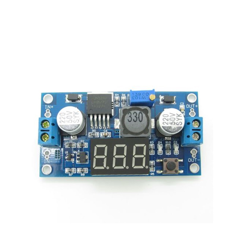
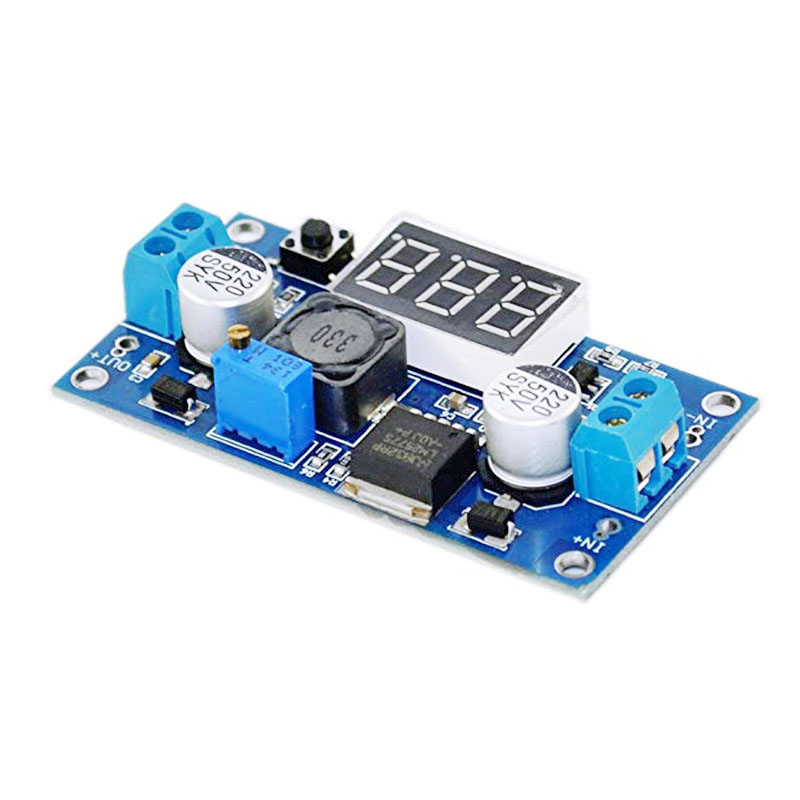
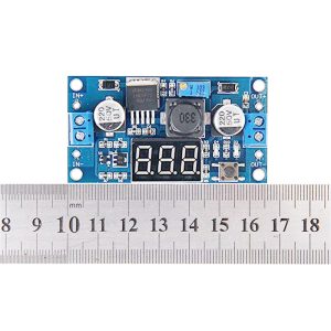
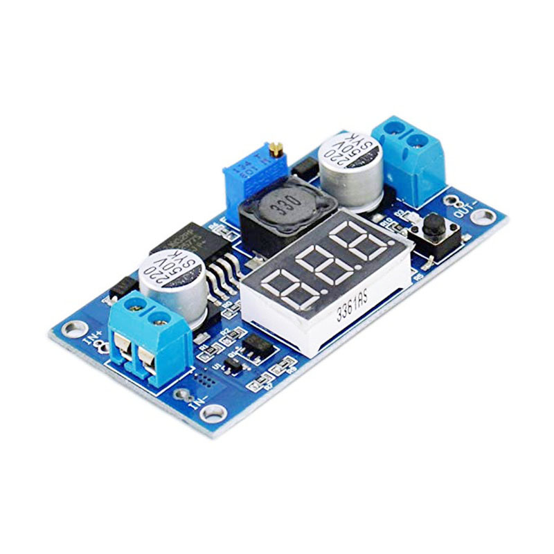
The LM2577 DC-DC Digital Voltmeter Booster Module is a high-performance step-up (boost) switching regulator that combines the reliable LM2577 chip with a built-in digital voltmeter display. This all-in-one module efficiently converts lower DC voltages (from 3V) into higher, adjustable output voltages up to 35V, while allowing you to monitor both input and output voltages in real-time without an external multimeter .
Based on the Texas Instruments LM2577 switching regulator, this module operates at a fixed 52 kHz switching frequency and achieves conversion efficiencies of up to 80% . The integrated 3-digit LED display can be toggled between input and output voltage readings with a single button, making it incredibly convenient for benchtop use, battery-powered projects, and field adjustments.
The module features a high-precision multi-turn potentiometer for output voltage adjustment, a power-down memory function that recalls your last voltage setting, and the ability to turn off the display to save power . Whether you’re powering 12V devices from a 5V USB source, charging battery packs, or creating a variable bench power supply, this module provides a complete, user-friendly solution.
Key Features
-
Integrated 3-Digit LED Display: Shows input or output voltage at the press of a button (±0.1V accuracy, 0-40V range), eliminating the need for an external multimeter
-
Adjustable Output Voltage: Continuously adjustable from 4V to 35V via onboard precision multi-turn potentiometer
-
Wide Input Voltage Range: Accepts DC input from 3V to 34V, compatible with 3.7V Li-ion batteries, 5V USB, 12V car batteries, and 24V industrial supplies
-
3A High Output Current: Capable of delivering up to 3A output current (2.5A continuous recommended). Input current can reach 3A
-
High Conversion Efficiency: Up to 80% efficiency with 52 kHz fixed-frequency oscillator, minimizing power loss and heat generation
-
Built-in Protection Features: Includes current limiting, undervoltage lockout, thermal shutdown, and soft-start function to reduce inrush current during startup
-
Power-Down Memory Function: Automatically remembers and displays the last measured voltage when power is restored
-
Display On/Off Control: Press and hold the button for 3 seconds to turn off the LED display, saving power in battery applications; press again to reactivate
-
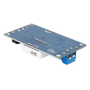
Screw Terminal Connections: Features wiring terminals for easy, solderless installation
Technical Specifications
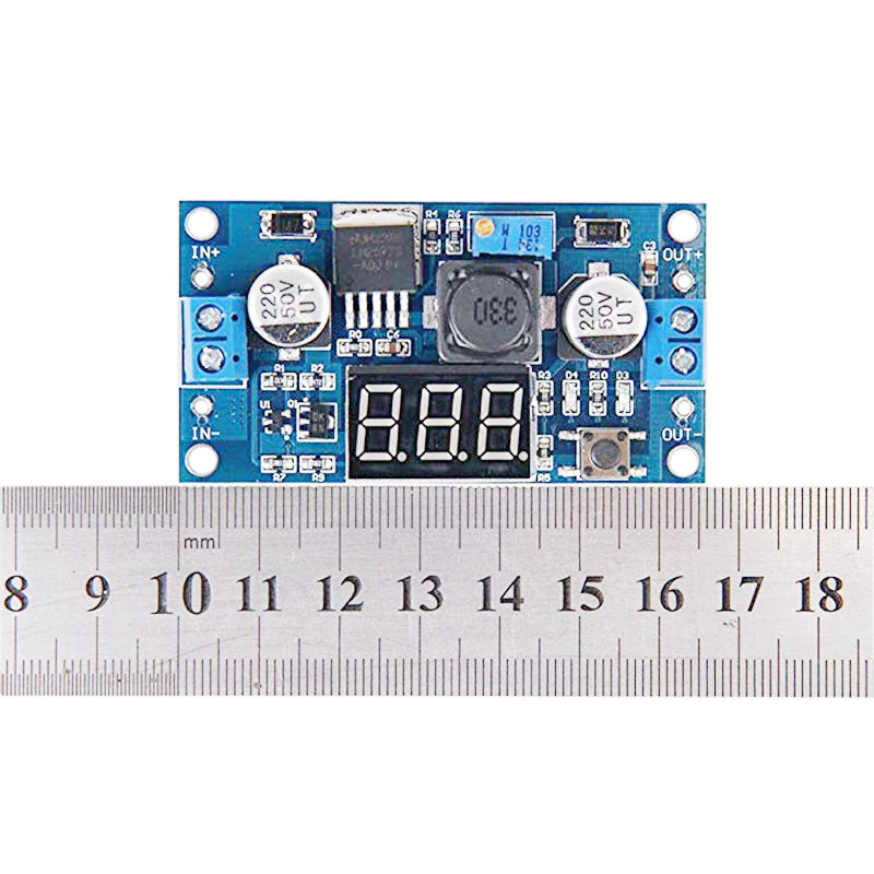
Pinout & Interface Guide
Input Side (Power Source)
-
IN+ (VIN): Connect to the positive terminal of your DC power source (e.g., 3.7V battery, 5V USB, 12V car adapter)
-
IN- (GND): Connect to the negative terminal (ground) of your DC power source
Output Side (Load Connection)
-
OUT+ (VOUT): Connect to the positive terminal of your device (e.g., 12V LED strip, battery to charge)
-
OUT- (GND): Connect to the negative terminal (ground) of your device
User Controls & Display
-
Precision Potentiometer: Multi-turn potentiometer for output voltage adjustment. Clockwise increases voltage, counter-clockwise decreases voltage
-
Display Button (Right Key): Press to toggle display between input voltage (“IN” indicator) and output voltage (“OUT” indicator). Press and hold for 3 seconds to turn display ON/OFF
-
3-Digit 7-Segment Display: Shows voltage value with 0.1V resolution
Status Indicators
Usage Guide
Wiring Instructions
IMPORTANT: Always disconnect the input power source before wiring. The output voltage must be higher than the input voltage for boost operation.
-
Connect Input: Connect the positive wire of your DC power source to IN+ and the negative wire to IN-
-
Set Initial Output: Before connecting your load, turn the blue potentiometer fully counter-clockwise to set output to minimum voltage (approximately 4V)
-
Power On & Adjust: Apply input power. The display will show voltage. Press the button to select “OUT” mode. Slowly turn the potentiometer clockwise while monitoring the display until reaching your desired voltage
-
Connect Load: Turn off power, connect your device to OUT+ and OUT-, then re-apply power
Display Operation
Example 1: 3.7V Li-ion Battery to 5V USB Output
Power a USB device from a single 18650 lithium battery.
-
Connect the 3.7V battery’s positive terminal to IN+ and negative to IN-
-
Press the button to select “OUT” display mode
-
Apply power and carefully adjust the potentiometer until the display reads 5.0V
-
Connect your USB device to the output terminals
Note: The output voltage must be higher than the input voltage. A 3.7V input can be boosted to 5V, 9V, 12V, etc.
Example 2: 5V USB to 12V LED Lighting
Power 12V LED strips from a USB power bank or phone charger.
-
Connect the 5V USB source to IN+ and IN-
-
Press the button to select “OUT” display mode
-
Adjust the potentiometer until the display reads 12.0V
-
Connect your 12V LED strip to the output terminals
-
The module will boost 5V to 12V for your lighting
Example 3: Variable Bench Power Supply
Create a variable benchtop power supply from a fixed voltage source.
-
Use a 12V-24V power adapter as the input source
-
Mount the module in a small enclosure with binding posts
-
Use the built-in display to monitor output voltage
-
Adjust output from 4V to 35V as needed for testing circuits
Important Considerations
-
Step-Up Only: This is a boost (step-up) converter only. The output voltage must always be higher than the input voltage. For step-down applications, use a buck converter
-
Heat Management: For loads above 2A, a heatsink is strongly recommended. At 3A continuous, the module will get hot—ensure adequate ventilation
-
Input Current Requirement: When boosting voltage, input current is higher than output current. For 12V 1A output from 5V input (80% efficiency), input current will be approximately 3A. Ensure your power source can supply sufficient current
-
Potentiometer Troubleshooting: If the output voltage cannot be adjusted (output equals input voltage), try turning the potentiometer counter-clockwise 20 or more full rotations, then adjust clockwise
-
Minimum Input Voltage: The voltmeter requires at least 3V input to operate accurately
Q: What is the difference between a boost converter and a buck converter?
A boost converter (step-up) increases a lower input voltage to a higher output voltage (e.g., 5V to 12V). A buck converter (step-down) decreases a higher input voltage to a lower output voltage. This module is a boost converter only.
Q: Can this module decrease voltage (buck)?
No. This is a boost (step-up) converter only. The output voltage must always be higher than the input voltage. If you apply 12V input and set the output to 5V, the output will follow the input (minus a diode drop) and cannot be regulated down
Q: What is the maximum output current I can draw from this module?
The module is rated for a maximum of 3A peak. For long-term reliability, it is recommended to stay within 2.5A, and a heatsink should be used for loads above 2A
Q: What is the minimum input voltage required for the voltmeter to work?
The voltmeter requires at least 3V input to operate accurately. Below this voltage, the display may not function correctly
Q: What does the power-down memory function do?
The module remembers the last displayed voltage setting (input or output) and will show that same measurement when power is restored, saving you from having to reselect the display mode
Q: The module gets hot. Is this normal?
Some heat is normal, especially under high load (near 3A). If it is too hot to touch, you should:
-
Attach a heatsink to the LM2577 IC
-
Reduce the load current to below 2.5A
-
Ensure adequate airflow around the module
Q: What is the efficiency of this converter?
The LM2577 achieves up to 80% conversion efficiency under optimal conditions . This is significantly higher than linear regulators but lower than modern synchronous boost converters. Efficiency varies with input/output voltage differential and load current.
Q: Why is my output voltage not changing when I turn the potentiometer?
The potentiometer may require multiple rotations. Try turning it counter-clockwise 20 or more full rotations, then adjust clockwise while monitoring the display or a multimeter .
Q: The output voltage equals the input voltage and won't adjust. What's wrong?
This usually indicates the module is not boosting. Try turning the potentiometer counter-clockwise 20 or more turns. If still no change, the module may be damaged .
Q: How do I turn off the LED display to save power?
Press and hold the button for 3 seconds to turn off the display. Press the button again to turn it back on
Q: Can I use this module to charge batteries?
Yes, with caution. The LM2577 can be used to charge batteries in constant voltage (CV) mode. However, for lithium batteries, you need a proper constant current/constant voltage (CC/CV) charging profile. If using this module, set the output to the battery’s float voltage and use an external current-limiting resistor or dedicated charger circuit.
Q: Can I connect the input in reverse?
No. Reversing the input polarity may damage the module. Always double-check your wiring before applying power.
Q: The display shows the wrong voltage. How can I fix this?
The voltmeter has a specified accuracy of ±0.1V . If you need more precise readings, use an external multimeter to verify and adjust the output voltage accordingly.
Q: What can I build with this boost converter module?
Popular applications include:
-
USB power banks: Boost 3.7V Li-ion battery to 5V for phone charging
-
LED lighting: Power 12V LED strips from 5V USB or 3.7V batteries
-
Battery charging: Charge higher voltage battery packs (e.g., charge 4S Li-ion from 12V)
-
Laptop car chargers: Boost 12V car battery to 19V for laptop power
-
DIY bench power supplies: Create variable voltage sources up to 35V with built-in monitoring
Q: Can I use this module to power a 12V device from a 5V USB power bank?
Yes. Connect the 5V USB power bank to the input, set the output to 12V, and you can power 12V devices like LED strips, fans, or small pumps. Ensure the USB power bank can supply sufficient current (for 12V 1A output, expect ~2.5A input draw).
Q: Can I run two modules in parallel for more current?
Not recommended. Running switching regulators in parallel without proper current-sharing circuitry can cause one module to supply most of the load, leading to overheating and failure. For higher current, use a single higher-rated converter.
Q: Can I use this module with a solar panel?
Yes. The module can boost the variable voltage output from a solar panel to a stable voltage for charging batteries or powering devices. Ensure the solar panel’s open-circuit voltage does not exceed the module’s maximum input rating (34V).