Product Overview
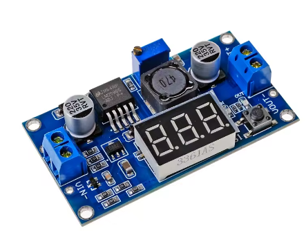
The LM2596 3A Buck Converter Module with Digital Display is a high-precision, adjustable step-down switching regulator that combines the proven performance of the Texas Instruments LM2596 chip with a convenient built-in 3-digit LED voltmeter. This all-in-one module allows you to monitor both input and output voltages in real-time, eliminating the need for a separate multimeter during voltage adjustment .
Based on the industry-standard LM2596 switching regulator, this module efficiently converts higher DC voltages (from 4.0V to 40V) into a lower, continuously adjustable output ranging from 1.25V to 37V . With a maximum output current of 3A and conversion efficiency up to 92%, it runs much cooler and wastes significantly less power than traditional linear regulators, making it ideal for battery-powered or enclosed applications .
The standout feature of this module is its 3-digit 7-segment display, which can show either input or output voltage at the press of a button. This is particularly useful for applications like powering 12V LED strips from a 24V supply, charging 5V devices from a 12V battery, or creating a custom variable benchtop power supply without needing external measurement tools .
Key Features
-
Integrated 3-Digit LED Display: Shows input or output voltage in real-time with a push-button switch, eliminating the need for an external multimeter during adjustment
-
Adjustable Output Voltage: Continuously adjustable from 1.25V to 35V (37V max) via onboard precision multi-turn potentiometer
-
Wide Input Voltage Range: Accepts DC input from 3.2V to 40V, compatible with 5V, 12V, 24V, and 36V systems
-
3A High Output Current: Capable of delivering up to 3A peak output current. For continuous operation, 2A is recommended; a heatsink is advised for loads above 2A or power exceeding 10W
-
High Conversion Efficiency: Up to 92% efficiency with 150kHz switching frequency, minimizing power loss and heat generation
-
Low Output Ripple: Output ripple ≤30mV, suitable for sensitive electronics like microcontrollers and sensors
-
Built-in Protection: Includes thermal shutdown and current limit protection to safeguard the module and your connected devices
-
Display Self-Calibration: The voltmeter can be calibrated to your multimeter for precise readings
-
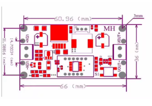
Compact Design: Small PCB footprint (approx. 66mm × 36mm × 12mm) with screw terminals for easy, solderless wiring
Technical Specifications
Pinout & Interface Guide
Input Side (Power Source)
-
IN+ (VIN): Connect to the positive terminal of your DC power source (e.g., 12V battery, 24V power supply)
-
IN- (GND): Connect to the negative terminal (ground) of your DC power source
Output Side (Load Connection)
User Controls & Display
-
Precision Potentiometer: Blue multi-turn potentiometer for output voltage adjustment. Clockwise increases voltage, counter-clockwise decreases voltage
-
Display Button (Right Key): Press to toggle display between input voltage (“IN” LED) and output voltage (“OUT” LED)
-
3-Digit 7-Segment Display: Shows voltage value with 0.1V resolution
Usage Guide
Wiring Instructions
IMPORTANT: Always disconnect the input power source before wiring. The input voltage must be at least 1.5V higher than the desired output voltage .
-
Connect Input: Connect the positive wire of your DC power source to IN+ and the negative wire to IN-
-
Connect Multimeter (Recommended): Attach a multimeter to the output terminals for accurate voltage monitoring during initial setup
-
Set Initial Output: Before connecting your load, turn the blue potentiometer fully counter-clockwise to set output to minimum voltage
-
Power On & Adjust: Apply input power. The display will show voltage. Press the button to select “OUT” mode. Slowly turn the potentiometer clockwise while monitoring the display/multimeter until reaching your desired voltage
-
Connect Load: Turn off power, connect your device to OUT+ and OUT-, then re-apply power
Display Calibration
The built-in voltmeter can be calibrated against a reference multimeter for precise readings :
-
Enter Calibration Mode: Press and hold the right button for 3 seconds until the display flashes
-
Select IN or OUT: Press button to select which voltage to calibrate (indicated by IN/OUT LED)
-
Adjust Value: Click the button to increase the displayed value. (Note: Each unit is less than 0.1V; multiple presses may be needed to change 0.1V)
-
Exit Calibration Mode: Press and hold the button for 3 seconds again to save settings
Turning Off the Display
To conserve power or reduce light pollution, the display can be turned off :
Example Applications
1. Powering 12V LED Strip from 24V Supply
-
Connect 24V power supply to IN+ and IN-
-
Adjust output to 12.0V using the display
-
Connect 12V LED strip to output terminals
2. 48V E-Bike to 5V USB Charger
3. Variable Bench Power Supply
-
Use a 24V or 36V power adapter as input
-
Adjust output from 1.25V to 35V as needed
-
Use the display to monitor output voltage without an external meter
Important Considerations
-
Step-Down Only: This is a buck converter only. Output voltage must be lower than input voltage by at least 1.5V
-
Heat Management: For continuous loads above 2A (or output power >10W), attach a heatsink to the LM2596 IC. At 3A, the module will get hot
-
Initial Adjustment: If you cannot adjust the output voltage, try turning the potentiometer counter-clockwise 10 or more full rotations, then adjust clockwise
-
No Reverse Polarity Protection: Most modules lack reverse polarity protection. Double-check wiring before applying power
Q: What is the difference between a buck converter and a boost converter?
A buck converter (step-down) decreases a higher input voltage to a lower output voltage (e.g., 24V to 5V). A boost converter (step-up) increases a lower input voltage to a higher output voltage. This module is a buck converter only.
Q: Can this module increase voltage (boost)?
No. This is a buck (step-down) converter only. The output voltage must always be lower than the input voltage. The input must be at least 1.5V higher than the desired output for stable regulation .
Q: What is the maximum output current I can draw from this module?
The module is rated for a maximum of 3A peak but only for short durations. For continuous, reliable operation, it is recommended to stay within 2A . For loads above 2A (or output power >10W), a heatsink is strongly recommended .
Q: Why does my display show the input voltage even after adjusting the potentiometer?
The display defaults to showing input voltage (“IN” LED lit). Press the right button once to switch to output voltage mode (“OUT” LED lit). Adjusting the potentiometer will now change the displayed output voltage .
Q: What is the minimum voltage difference required between input and output?
The input voltage must be at least 1.5V higher than the desired output voltage for proper regulation. For example, to get 5V output, you need at least 6.5V input .
Q: The module gets hot. Is this normal?
Some heat is normal, especially under high load (near 2A). If it is too hot to touch, you should:
-
Attach a heatsink to the LM2596 IC’s metal tab
-
Reduce the load current to below 2A
-
Ensure adequate airflow around the module
Q: How accurate is the built-in voltmeter?
The voltmeter accuracy can be calibrated against your multimeter. The module includes a self-calibration function to adjust the displayed value for precise readings
Q: Can I power this module from a 48V e-bike battery?
Yes, but check specifications. The absolute maximum input voltage is 40V. A fully charged 48V battery reaches 54.6V, which exceeds this limit and may damage the module. For 48V systems, use the LM2596HVS variant (supports up to 60V) instead .
Q: Why is my output voltage not changing when I turn the potentiometer?
The potentiometer may require multiple rotations. Try turning it counter-clockwise 10 or more full rotations, then adjust clockwise while monitoring the display or a multimeter .
Q: The module has power (display is on) but there is no output voltage.
Follow this checklist:
-
Check the display mode—ensure “OUT” LED is lit (press button to switch)
-
The potentiometer may be turned fully counter-clockwise (minimum voltage). Try turning it clockwise
-
Check that there is no short circuit on the output terminals
-
Verify that your input voltage is at least 1.5V higher than your target output voltage
Q: Can I connect the input in reverse?
Not recommended. Most modules do not have built-in reverse polarity protection. Reversing the input polarity will damage the module. Some variants include protection, but always double-check your wiring before applying power
Q: The output voltage equals the input voltage and won't adjust. What's wrong?
This usually indicates a faulty module. If the output voltage matches the input voltage regardless of potentiometer adjustment, the LM2596 IC may have failed short-circuit. Replace the module
Q: Can I use this module to charge a 12V lead-acid or lithium battery?
With caution. The module provides constant voltage (CV) but lacks a dedicated constant current (CC) charging profile. For battery charging, you need proper CC/CV charging. If you still choose to use this module, set the output to the battery’s float voltage (e.g., 12.6V for 3S Li-ion) and limit current externally
Q: What can I build with this buck converter module?
Popular applications include:
-
Power 12V LED strips from 24V power supplies
-
USB charging ports in vehicles (12V/24V to 5V)
-
Variable bench power supplies for testing electronics
-
Power microcontrollers (Arduino, ESP8266, Raspberry Pi) from higher voltage batteries
-
48V e-bike to 12V accessories (use LM2596HVS variant for 48V input)
Q: Can I run two modules in parallel for more current?
Not recommended. Running switching regulators in parallel without current-sharing circuitry can cause one module to supply most of the load, leading to overheating and failure. For higher current, use a single higher-rated converter or separate modules for independent subsystems
Q: Can I use this module to power a 3.3V ESP8266 from a 12V battery?
Yes. Set the output voltage to 3.3V using the potentiometer. Ensure the load current does not exceed 2A continuous. The ESP8266 typically draws less than 300mA, so this is well within the module’s capabilities