Product Overview
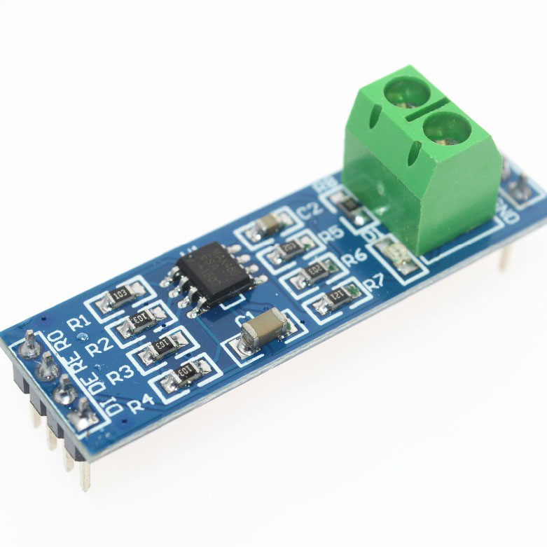
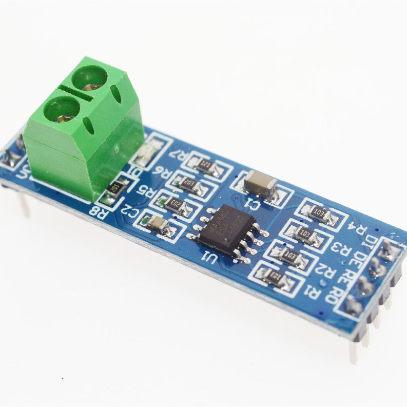
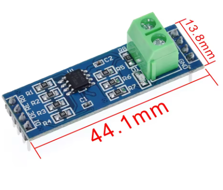
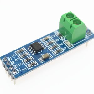
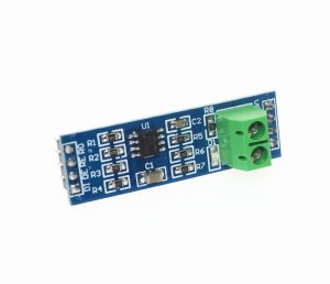
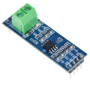
The MAX485 TTL to RS485 Converter Module is a compact, high-performance interface module designed to convert UART/TTL serial signals to the industry-standard RS485 differential communication protocol. Powered by the reliable MAX485 chip from Maxim Integrated, this module allows your microcontroller (Arduino, ESP32, STM32, Raspberry Pi) to communicate over long distances (up to 1200 meters) in electrically noisy industrial environments .
RS485 is the go-to protocol for industrial automation, building management systems, and multi-device networks. Unlike standard TTL serial (which is limited to short distances), RS485 uses differential signaling on twisted-pair wires (A and B lines) to provide superior noise immunity and allows for multi-drop networks with up to 32 devices on a single bus . The MAX485 transceiver handles the heavy lifting of converting these signals, making it the perfect choice for Modbus RTU networks, DMX lighting control, and countless DIY and professional applications. It also features a low-power shutdown mode and boasts driver/receiver enable pins for half-duplex communication control .
Key Features
-
Long-Distance Communication: Supports data transmission up to 1200 meters (4000 ft) at lower data rates .
-
High-Speed Data Transfer: Capable of data rates up to 2.5 Mbps, suitable for high-speed industrial data logging .
-
Multi-Device Networking: The standard 1/8th unit-load receiver input impedance allows up to 32 transceivers on a single RS485 bus (multi-drop configuration) .
-
Industrial Noise Immunity: RS485 differential signaling ensures reliable communication in electrically noisy environments.
-
5V Logic Compatible: Designed to work with 5V microcontrollers (Arduino, STM32) .
-
Low Power Consumption: Features a low-current shutdown mode (as low as 0.1µA) and supply current draw between 120µA and 500µA .
-
Simple Half-Duplex Operation: Ideal for efficient 2-wire bus communication with automatic transceiver direction control via MCU pins.
-
Onboard Terminal Block: Includes a 5.08mm pitch 2-pin terminal block for robust and secure connection of RS485 A/B bus wires .
-
Receiver Fail-Safe: Ensures a logic-high output if the receiver input is open circuit, preventing floating data issues .
Technical Specifications
Pinout & Interface Guide
The module provides two distinct interfaces: the TTL side (connecting to your microcontroller) and the RS485 bus side (connecting to the network).
TTL Side (5V Microcontroller Interface)
Note: For standard half-duplex operation, RE and DE are often shorted together and controlled by a single MCU pin.
RS485 Bus Side (Network Interface)
Usage Guide
Wiring Instructions
IMPORTANT: Ensure that all devices on the RS485 bus share a common ground reference.
Standard Half-Duplex Network Setup
-
Connect Power: Provide a stable +5V DC supply to the VCC and GND pins.
-
Connect to Microcontroller:
-
Link R0 to the MCU’s RX pin.
-
Link DI to the MCU’s TX pin.
-
Use a jumper wire to short the RE and DE pins together. Connect this node to a free GPIO pin (e.g., Pin 2). This single pin will control the direction of communication.
-
Connect to RS485 Bus:
-
Terminate the RS485 bus by placing a 120Ω resistor across the A and B terminals at the two farthest ends of the cable run .
-
Connect the A terminal of all modules together.
-
Connect the B terminal of all modules together.
Direction Control Logic
Since the MAX485 operates in half-duplex mode, you must manually control the RE/DE pin to switch between transmission and reception:
Arduino Example Code
This simple sketch demonstrates how to use the module to receive RS485 data. It sets the module to “listen” mode, and when data is available, it prints it to the Serial Monitor.
#define RS485_CTRL 2
void setup() {
Serial.begin(9600);
Serial1.begin(9600);
pinMode(RS485_CTRL, OUTPUT);
digitalWrite(RS485_CTRL, LOW);
}
void loop() {
if (Serial1.available()) {
char c = Serial1.read();
Serial.print(c);
}
}
(To transmit data, you would first set digitalWrite(RS485_CTRL, HIGH);, write to Serial1, wait for transmission, and then set the pin LOW again.)
Q: How far can I run the RS485 communication cable?
RS485 is designed for long distances. You can reliably run cable up to 1,200 meters (approximately 4,000 feet) , particularly at lower baud rates like 9600bps .
Q: How many devices can I connect to a single RS485 bus with this module?
The MAX485 chip is a standard 1-unit load device. This allows you to connect up to 32 devices (MAX485 transceivers) on a single multi-drop RS485 network .
Q: What is the difference between RS485 and standard TTL serial?
TTL serial is single-ended (transmit on one wire, receive on another) and is susceptible to noise over long distances. RS485 uses differential signaling (the voltage difference between “A” and “B” wires). This difference cancels out electrical noise, allowing for very long cable runs and stable communication in factory/industrial environments.
Q: Do I need termination resistors?
Yes, for reliable long-distance or high-speed communication. Place a 120Ω resistor across the A and B terminals at the two most distant nodes on the bus. This matches the cable’s characteristic impedance and prevents signal reflections that can corrupt data .
Q: Is this module compatible with 3.3V systems like ESP32 or Raspberry Pi?
This specific MAX485 module is designed for 5V logic. Direct connection to 3.3V systems may cause unreliable operation or damage. For 3.3V systems, consider using the pin-compatible MAX3485 module instead .
Q: Why can't I get any data to transmit or receive?
The most common issue is forgetting to control the RE/DE pins. The MAX485 must be told when to listen and when to talk. Ensure your code is correctly setting the RE/DE pin HIGH for transmit and LOW for receive .
Q: My data is garbled or there are errors. What is wrong?
Check the following:
-
Termination: Are the 120Ω termination resistors installed at the ends of the long cable?
-
Baud Rate: Ensure all devices on the bus (Master, Slave, Serial Monitor) are configured for the exact same baud rate.
-
Wiring: The A and B lines can be swapped. Try swapping the A and B wires on one device.
Q: What causes the bus to lock up or stop working?
If a device fails (e.g., a driver gets “stuck” in the on state), it can hold the bus lines in a dominant state, blocking all other devices. Some advanced transceivers have a “fail-safe” feature, but on a standard bus, you must identify and remove the faulty node .
Q: What is the RS485 module used for?
It is used to convert UART signals to RS485 levels, allowing microcontrollers to communicate over long distances or in noisy environments. Common applications include reading energy meters, programming industrial PLCs, controlling Modbus devices, and operating DMX lighting.
Q: Can I use this module for DMX lighting control?
Yes. DMX512 (used for stage and architectural lighting) is electrically identical to RS485. You can use this module to build a DMX controller or receiver for LED light shows.
Q: What is the data rate limit for long cables?
The relationship is inversely proportional:
-
At 9600 baud, you can achieve up to 1200m.
-
At 2.5 Mbps, the cable length is limited to approximately 30m. For best performance, consult the cables specifications .