Product Overview
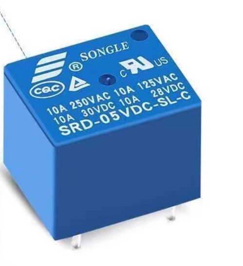
The SRD-05VDC-SL-A is a high-quality, subminiature electromagnetic relay manufactured by Songle Relay (Ningbo Songle Relay Co., Ltd.), one of the most trusted names in the relay industry . This 4-pin, 1 Form A (SPST-NO) relay is designed to switch loads up to 10A at 250V AC or 30V DC, making it an ideal choice for a wide range of applications including home appliances, office equipment, audio systems, and industrial control circuits .
With a 5V DC coil, this relay is perfectly suited for standard 5V microcontroller applications such as Arduino, ESP32, and other 5V logic systems . The relay features a sealed construction that protects the internal contacts from dust, humidity, and environmental contaminants, ensuring long-term reliability even in demanding conditions . It is recognized by major safety agencies including UL, CUL, and TUV, providing confidence for both hobbyist and commercial applications .
The SRD series relay employs a simple magnetic circuit design that enables high-density PCB mounting while maintaining a compact footprint. Its SPST-NO (Single Pole Single Throw, Normally Open) configuration provides straightforward ON/OFF control, making it ideal for applications where the load should be OFF by default and turned ON when the relay is activated .
Key Features
-
SPST-NO Contact Configuration (1 Form A): Single Pole Single Throw, Normally Open contact configuration with 4 pins
-
10A High Switching Capacity: Contacts rated for 10A at 250V AC or 10A at 30V DC, suitable for controlling lights, fans, pumps, and small motors
-
5V DC Coil Voltage: Standard operating voltage of 5V DC with a coil resistance of approximately 70Ω and power consumption of 0.36W (360mW)
-
Compact Subminiature Design: Small footprint measuring approximately 19.2mm × 15.6mm × 15.8mm, ideal for high-density PCB mounting
-
Sealed Construction: Protects internal contacts from dust, moisture, and environmental contaminants for enhanced reliability
-
Safety Agency Approvals: UL, CUL, and TUV recognized for reliable performance in commercial and industrial applications
-
Fast Switching Time: Typical operate and release time of ≤10ms, suitable for most control applications
-
Wide Operating Temperature: Rated for operation from -40°C to +85°C, suitable for demanding environments
Technical Specifications
Pinout & Interface Guide
The SRD-05VDC-SL-A features 4 pins arranged in a standard configuration :
Wiring Diagram
[Coil Connection]              [Switch Contacts]
    +  ----------
     |                         COM ---o
    [Relay Coil]               NO  ---o (Open when relay OFF)
     |                         (Closed when relay ON)
    -  ----------
Contact State Summary
Usage Guide
Driving the Relay
The SRD-05VDC-SL-A requires approximately 71.4mA of current to energize the coil (calculated from I = V/R = 5V / 70Ω) . This is near the maximum current rating of some microcontroller pins (typically 20mA–40mA), so a transistor driver circuit is strongly recommended .
Recommended Driver Circuit (with NPN Transistor)
    +5V --------[Relay Coil]----+----- +5V (for logic)
                                  |
                                  |/ C
                     Arduino Pin ----|  2N2222 or BC547
                                  |\ E
                                  |
                                GND

                   [Flyback Diode] (1N4148 or 1N4007)
                        +----|<|----+
                        |           |
                  [Relay Coil]       |
                        |           |
                      GND           |
                        +-----------+
Direct Drive (for high-current microcontrollers)
Some microcontrollers with high-current output pins (e.g., some Arduino models can source up to 40mA per pin) may drive the relay directly, but a transistor driver is recommended for long-term reliability.
Basic Arduino Control Example
const int relayPin = 7;
void setup() {
pinMode(relayPin, OUTPUT);
digitalWrite(relayPin, LOW);
}
void loop() {
digitalWrite(relayPin, HIGH);
delay(5000);
digitalWrite(relayPin, LOW);
delay(5000);
}
ESP32 / ESP8266 Control Example
Since ESP32 and ESP8266 operate at 3.3V logic, they cannot directly drive the 5V relay coil. Use a transistor driver circuit with a separate 5V supply for the relay coil.
const int relayPin = 5;
void setup() {
pinMode(relayPin, OUTPUT);
digitalWrite(relayPin, LOW);
}
void loop() {
digitalWrite(relayPin, HIGH);
delay(5000);
digitalWrite(relayPin, LOW);
delay(5000);
}
Load Connection Guidelines
For AC Loads (e.g., lights, fans):
-
Connect the Live (L) wire to the COM terminal
-
Connect the Load to the NO terminal
-
Connect the Neutral (N) wire directly to the load’s neutral
For DC Loads (e.g., motors, solenoids):
-
Connect the positive (+) supply to the COM terminal
-
Connect the load’s positive wire to the NO terminal
-
Connect the load’s negative wire directly to the power supply ground
Important: Flyback Diode
Always use a flyback diode (1N4148, 1N4007, or similar) across the relay coil terminals. When the coil is de-energized, it generates a high-voltage spike that can damage the transistor or microcontroller. The diode should be placed with the cathode (banded end) towards the positive supply and the anode towards the transistor collector .
Q: What is the difference between SRD-05VDC-SL-A and SRD-05VDC-SL-C?
The SRD-05VDC-SL-A is a 4-pin SPST-NO (Single Pole Single Throw, Normally Open) relay with only COM and NO contacts . The SRD-05VDC-SL-C is a 5-pin SPDT (Single Pole Double Throw) relay with COM, NO, and NC contacts . Choose the A version if you only need to turn a device ON when the relay is activated; choose the C version if you need both NO and NC functions.
Q: What is the maximum load this relay can handle?
The contacts are rated for 10A at 250V AC (resistive) or 10A at 30V DC . The maximum switching current can reach 15A under specific conditions . For inductive loads like motors or solenoids, it is recommended to derate to 5A–7A to account for startup surges.
Q: Can I use this relay directly with an Arduino, ESP32, or ESP8266?
The relay coil draws approximately 71.4mA at 5V , which exceeds the maximum current rating of most microcontroller pins (20mA–40mA). While some Arduino pins may handle this current, a transistor driver circuit is strongly recommended for reliability. ESP32 and ESP8266 (3.3V logic) cannot directly drive the 5V coil and require a transistor driver with a separate 5V supply .
Q: What is the purpose of the flyback diode?
When the relay coil is de-energized, it generates a high-voltage inductive kickback (often >50V) that can destroy the transistor or microcontroller. A flyback diode (1N4148, 1N4007) placed across the coil protects the driver circuit by providing a safe path for this energy to recirculate
Q: What is the difference between Form A and Form C contacts?
Form A (1 Form A) is SPST-NO (Single Pole Single Throw, Normally Open) —the contacts are open when the relay is de-energized . Form C (1 Form C) is SPDT (Single Pole Double Throw) —provides both NO and NC contacts for more flexible switching
Q: What is the coil resistance of this relay?
The SRD-05VDC-SL-A has a coil resistance of 70Ω ± 10% . This determines the current draw: I = V / R = 5V / 70Ω = 71.4mA
Q: What is the minimum voltage required to activate the relay?
The pick-up (pull-in) voltage is ≤ 75% of nominal voltage, meaning the relay will reliably activate when the coil voltage reaches 3.75V or higher . For consistent operation, it is recommended to use the full 5V.
Q: What is the drop-out voltage?
The drop-out (release) voltage is ≥ 10% of nominal voltage, so the relay will de-energize when the coil voltage drops below 0.5V
Q: What is the expected lifespan of this relay?
The relay is rated for 10 million mechanical operations (no load) and 100,000 electrical operations at the rated load . Actual lifespan depends on switching frequency and load type.
Q: Does the relay require a heatsink?
No. The relay is designed for PCB mounting with natural cooling. At 10A continuous load, the contacts may warm slightly, but no additional heatsink is required.
Q: Can I use this relay for 220V AC applications?
Yes. The contacts are rated for 10A at 250V AC, which is suitable for 220V/240V systems . Ensure proper insulation and clearance between coil and contact pins for safety.
Q: The relay clicks but my load doesn't turn on. What's wrong?
This indicates the coil is energizing but the load circuit is incomplete. Check:
-
The load’s wiring (COM to power source, NO to load)
-
The load’s neutral/ground is connected correctly
-
The load itself is functional
-
Contact continuity with a multimeter (should show closed when coil energized)
Q: The relay chatters or buzzes. What causes this?
Chatter usually indicates:
-
Insufficient coil voltage (below 3.75V)
-
Unstable power supply
-
Insufficient driver current
-
Loose connections
-
Contact contamination from switching inductive loads without proper suppression
Q: Can I use this relay in high-vibration environments?
The relay is rated for 10G shock resistance and can withstand vibration at 10-55Hz with 1.5mm amplitude. For extreme vibration applications, consider using a relay with additional mechanical reinforcement or a solid-state relay (SSR)
Q: What can I build with the SRD-05VDC-SL-A relay?
Popular applications include:
-
Home automation (lighting, fans, appliances)
-
Industrial equipment control
-
IoT projects with 5V microcontrollers (Arduino)
-
Remote power switching
-
Motor control (with appropriate contact rating)
-
HVAC system control
-
Security systems and alarms
Q: Can I use this relay with a 5V power supply from an Arduino?
Yes. The 5V pin on an Arduino can supply the necessary current if the relay is driven through a transistor circuit. Driving the coil directly from the 5V pin (without a transistor) is not recommended as it may exceed the board’s total current capacity.
Q: Is this relay suitable for controlling a pump or motor?
Yes, with derating. For inductive loads like motors, it is recommended to operate at 50–70% of the rated contact current (5A–7A) to account for startup surges. Consider adding a snubber circuit (RC network) across the contacts to suppress arcing.
Q: What is the maximum switching power this relay can handle?
The maximum switching power is 3750VA for AC loads (250V × 15A) and 300W for DC loads (30V × 10A)