TCA9548A 1 to 8 I2C 8-channel IIC

SKU: FA2011-1
Operating Voltage (VCC)

1.65V to 5.5V

I2C Clock Frequency

0 to 400 kHz (Standard & Fast Mode)

Default I2C Address

0x70 (Adjustable 0x70 to 0x77)

Channels

8 Bidirectional switches

I/O Logic Levels

5V Tolerant

ESD Protection

±2000V Human-Body Model

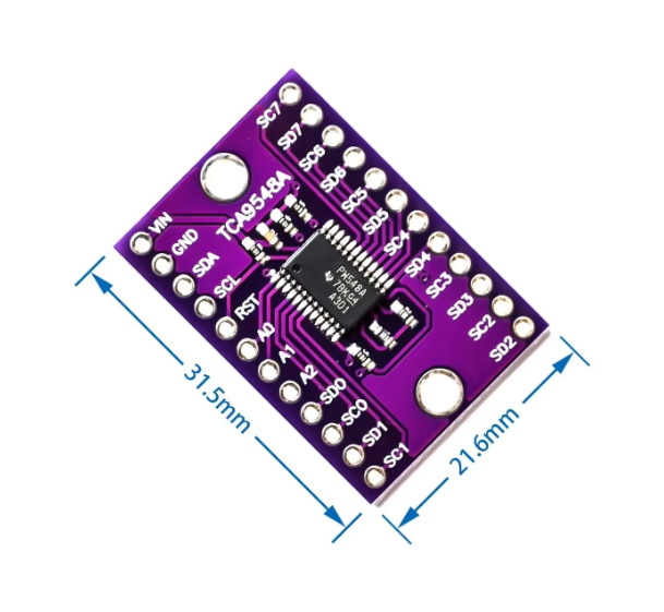
This TCA9548A 8-Channel I2C Multiplexer is the ultimate problem-solver for complex I2C projects. It allows you to connect up to 8 I2C devices with the same I2C address to a single microcontroller by acting as a “switchboard operator”.
Product Long Description
The TCA9548A is a bidirectional translating switch that expands your microcontroller’s I2C bus from one to eight independent downstream channels. This is essential when you have multiple identical sensors (like OLED displays or temperature sensors) that share the same hard-wired address, which would normally cause a conflict on the bus.
By sending a simple command to the TCA9548A, you can select which channel (0–7) to activate. Once a channel is selected, any subsequent I2C data is routed only to that specific channel. This module also supports voltage-level translation, allowing 1.8V, 2.5V, or 3.3V devices to communicate with a 5V controller seamlessly.
Key Features
  • 1-to-8 Expansion: Connect 8 separate I2C buses to a single host.
  • Address Conflict Resolution: Enables multiple devices with identical addresses on one system.
  • Configurable Host Address: Three address pins (A0, A1, A2) allow for 8 unique multiplexer addresses (0x70–0x77), enabling you to daisy-chain up to 8 multiplexers for a total of 64 I2C channels.
  • Bidirectional Translation: Supports voltage level shifting between 1.8V, 2.5V, 3.3V, and 5V.
  • Active-Low Reset: Dedicated RESET pin to recover from stuck downstream buses without cycling power.
  • Plug-and-Play Compatible: Works with Arduino, Raspberry Pi, ESP32, and any standard I2C/SMBus controller
Typical Usage
  1. Wiring: Connect the microcontroller’s SDA/SCL to the TCA9548A SDA/SCL. Power the board with 3.3V or 5V.
  2. Target Connection: Connect your sensors to the SD0/SC0 through SD7/SC7 ports.
  3. Channel Selection: In your code, write a single byte to the multiplexer’s address (0x70) indicating the channel you want to activate (e.g., write 0x01 to enable Channel 0).
  4. Communicate: Send standard I2C commands to your sensor as if it were directly connected to the microcontroller.
Q: Can I use multiple channels at the same time?

Yes, you can activate any combination of channels simultaneously by writing the corresponding bitmask to the control register. However, ensure there are no address conflicts among the devices on the combined channels.

Q: Do I need pull-up resistors on the output channels?

Yes. While many breakout boards include pull-ups on the main bus, the eight downstream channels usually require their own pull-up resistors to the desired voltage level.

Q: How do I change the I2C address of the multiplexer?

Use the A0, A1, and A2 pins. Connecting them to GND or VCC allows you to select an address between 0x70 and 0x77.

Q: What happens if one of my sensors hangs the I2C bus?

You can pull the RESET pin LOW to reset the multiplexer’s internal state and deselect all channels, allowing you to recover the main bus without a full system reboot