Wide Body ZIF Connector 40 Position 2.54mm Pitch

SKU: FA2024
Number of Positions

40 Pins (2 x 20)

Pitch (Pin Spacing)

2.54mm (0.1 inch)

Row Spacing

15.24mm (0.6 inch / Wide Body)

Contact Material

Phosphor Bronze (Tin or Gold plated)

Insulation Material

Glass-filled Polyester (UL94V-0)

Current Rating

1A

Insulation Resistance

1000MΩ min. at DC 500V

Operating Temp

-55°C to +150°C

Description
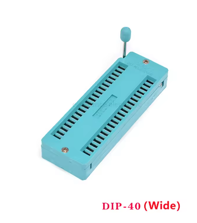
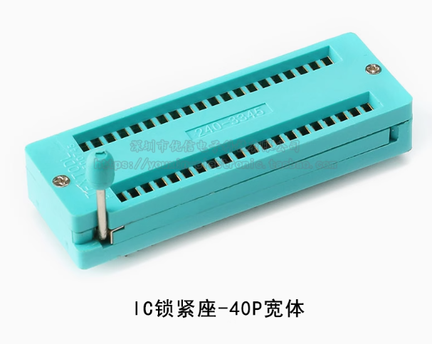
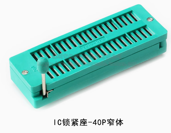
The 40-Pin Wide Body Zero Insertion Force (ZIF) Socket is a premium industrial-grade connector designed for frequent chip swapping and testing.Unlike standard IC sockets that require physical force to insert or remove components—often leading to bent or broken pins—this ZIF socket uses a specialized lever-actuated locking mechanism.
When the lever is raised, the internal contacts open completely, allowing a microcontroller (like the AT89S52 or Atmega series) or an EPROM chip to be dropped in with zero resistance. Once the lever is lowered, the socket’s high-conductivity contacts firmly grip the chip pins, ensuring a stable electrical connection. The “Wide Body” design accommodates both standard and slightly wider integrated circuits, making it an indispensable tool for programmers, development boards, and IC testing fixtures.
Key Features
  • Zero Insertion Force: Eliminates mechanical stress on delicate IC pins, significantly extending the life of your chips.
  • Durable Lever Action: Features a reinforced metal or high-strength plastic lever for thousands of reliable open/close cycles.
  • Universal Compatibility: Designed for any dual-inline package (DIP/DIL) integrated circuit with up to 40 pins and a standard 2.54mm (0.1″) pitch.
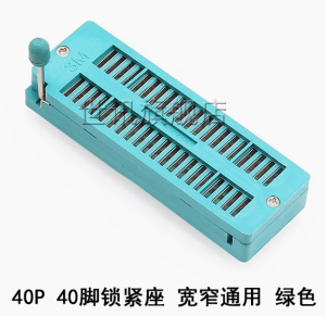
  • Wide Body Format: Specifically engineered to fit wider 0.6″ (15.24mm) row-spacing ICs, while remaining compatible with narrower 0.3″ chips.
  • Gold/Tin Plated Contacts: High-quality plating ensures low contact resistance and prevents oxidation over time.
  • Breadboard & PCB Friendly: Standard pin spacing allows for easy mounting onto prototype boards, specialized testers, or DIY development kits.
Usage Instructions
  1. Installation: Solder the ZIF socket onto your PCB or plug it into a compatible breadboard. Ensure the lever has enough clearance to move freely.
  2. Opening: Lift the lever to the vertical (90-degree) position. The internal clamps are now open.
  3. Insertion: Align your 40-pin (or smaller) IC with the holes. Drop the chip in; it should fall into place without any pushing.
  4. Locking: Push the lever down until it clicks into the horizontal position. The chip is now securely connected.
  5. Removal: Simply lift the lever and lift the chip out vertically.
Q: Can I use this for chips with fewer than 40 pins?

Yes. This 40-pin socket is “downward compatible.” You can insert 28-pin, 20-pin, or even 8-pin DIP chips. Just ensure you align them according to your circuit’s pin-1 orientation.

Q: Is this suitable for high-volume production testing?

Absolutely. Business customers use these sockets for “burn-in” testing and quality control where hundreds of chips must be programmed and verified daily.

Q: What is the benefit of the "Wide Body" over a standard ZIF?

Many high-performance microcontrollers and memory chips have a wider physical footprint (0.6″ between rows). A wide-body socket ensures you can test both standard and large-scale ICs without needing multiple socket types.

Q: Will the pins fit into a standard solderless breadboard?

Yes, the pins are spaced at the standard 2.54mm pitch. However, because ZIF sockets are wider than standard ICs, they may cover most of the tie-points on a small breadboard.

Q: Does the lever lock in place?
Yes, the lever is designed to lock firmly in the “down” position to prevent the chip from vibrating loose during operation or transit.