Product Overview
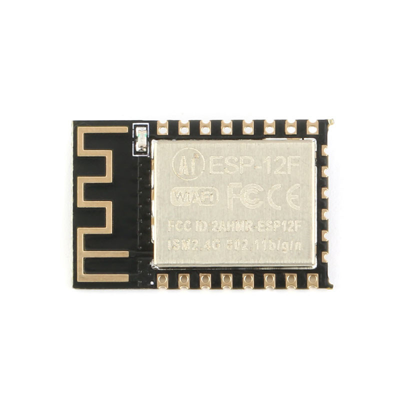
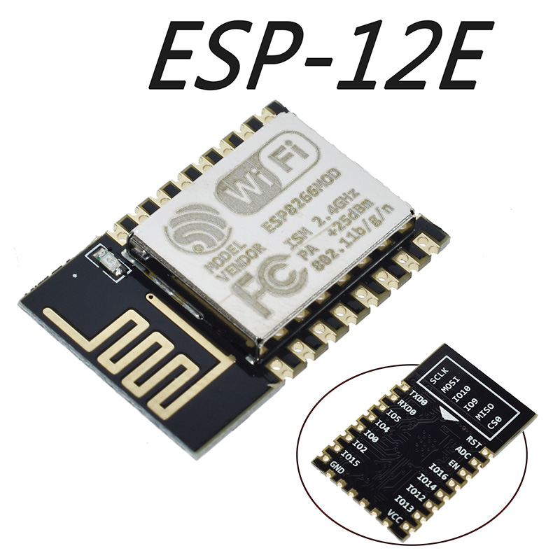
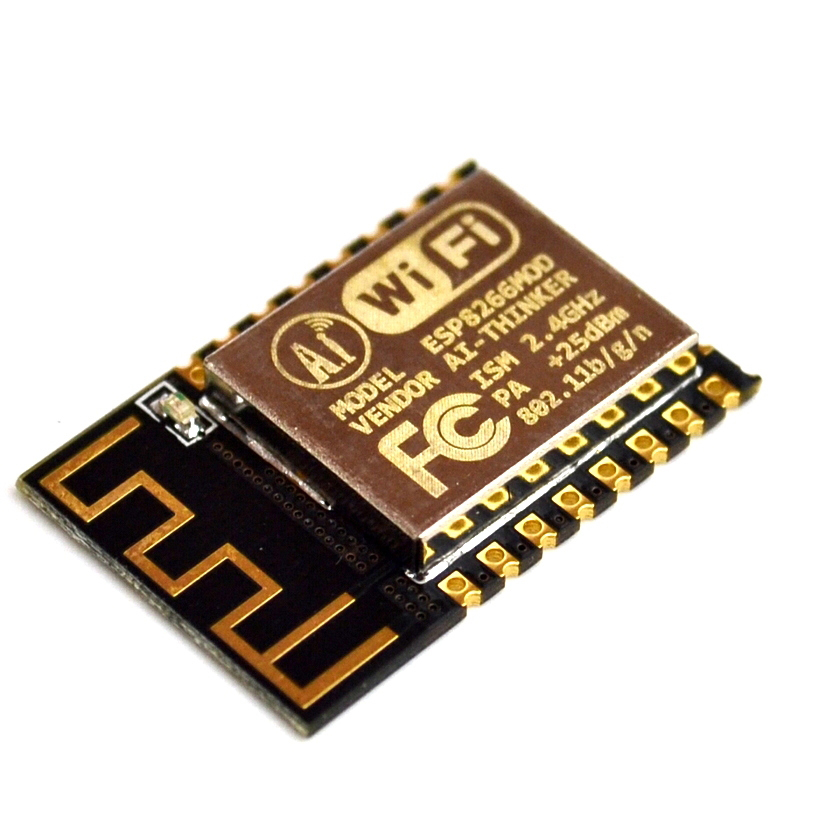
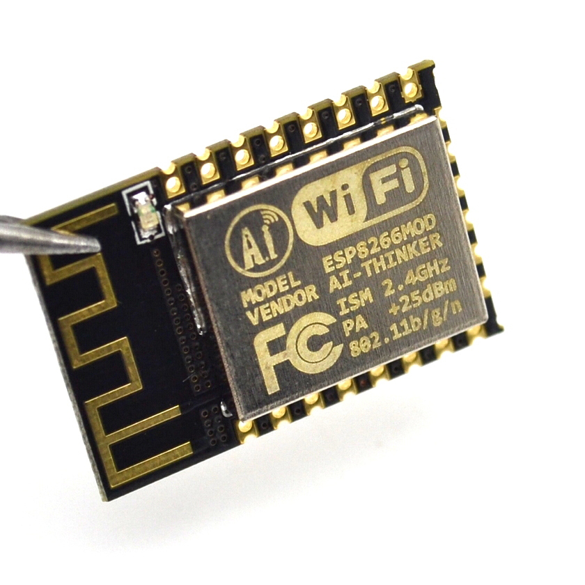
The ESP-12E ESP8266 Serial WiFi Module is a high-performance, feature-rich wireless communication module that has become the gold standard for IoT and embedded systems development. Manufactured by Ai-Thinker, one of the most trusted names in IoT modules, the ESP-12E is built around the revolutionary ESP8266EX chip from Espressif Systems —a complete Wi-Fi SoC (System on Chip) that integrates a 32-bit microcontroller, Wi-Fi radio, and TCP/IP protocol stack into a compact 16mm × 24mm package .
What sets the ESP-12E apart from simpler modules like the ESP-01 is its exceptional I/O availability. With 22 accessible pins, including 11 usable GPIOs, the ESP-12E provides the flexibility needed for complex projects without requiring external I/O expanders . It features a 4MB (32Mbit) flash memory , providing ample space for firmware, web interfaces, and OTA (Over-The-Air) updates .
The module supports 802.11 b/g/n Wi-Fi protocols with a maximum output power of +20dBm, ensuring robust wireless connectivity. It can operate in Station (STA), Access Point (AP), or Station+AP modes, giving you the flexibility to connect to existing networks or create your own . Whether you’re building smart home devices, industrial sensors, or wearable electronics, the ESP-12E delivers the processing power, I/O flexibility, and wireless reliability your project demands.
Key Features
-
Powerful 32-bit Processor: Built around the Tensilica L106 32-bit RISC processor running at up to 160 MHz, providing ample processing power for complex IoT applications without requiring an external microcontroller .
-
Rich I/O Capabilities: Features 11 usable GPIO pins with support for UART, SPI, I2C, I2S, PWM, and 10-bit ADC interfaces, allowing connection to a wide variety of sensors, actuators, and display devices .
-
4MB Flash Memory: Equipped with 4MB (32Mbit) of flash memory, providing abundant storage for firmware, web interfaces, and OTA (Over-The-Air) firmware updates .
-
Complete Wi-Fi Solution: Supports 802.11 b/g/n protocols with integrated TR switch, balun, LNA, power amplifier, and matching network. Delivers up to +20dBm output power with excellent receiver sensitivity .
-
Multiple Operating Modes: Supports Station (STA), Access Point (AP), and Station+AP modes, enabling devices to connect to existing networks or create their own.
-
Integrated TCP/IP Stack: Features an embedded LWIP protocol stack with support for TCP, UDP, HTTP, FTP protocols, enabling seamless internet connectivity .
-
Ultra-Low Power Consumption: Features multiple sleep modes with deep sleep current as low as 20µA , making it ideal for battery-powered applications .
-
Smart Configuration Support: Compatible with Smart Config and AirKiss one-click network configuration technologies, simplifying device onboarding .
-
Industrial Temperature Range: Rated for operation from -40°C to +125°C, making it suitable for demanding industrial environments and outdoor installations .
-
SMD Package for Automated Assembly: The SMD-22 package (half-hole pads) is designed for automated surface-mount assembly, making it suitable for large-scale production while remaining accessible for hand soldering .
-
Comprehensive Security: Supports WPA/WPA2 security protocols, ensuring secure wireless communication .
Technical Specifications
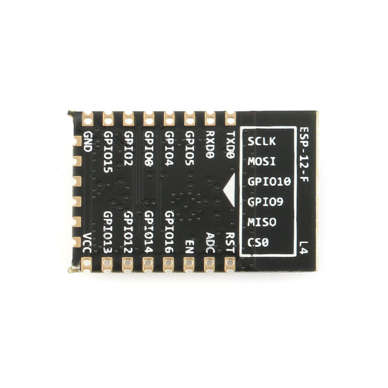
Pinout & Interface Guide
The ESP-12E features a 22-pin SMD package with half-hole pads for easy soldering. The pin definitions are as follows :
Important Boot Mode Configuration
The ESP-12E’s boot mode is determined by the state of GPIO0, GPIO2, and GPIO15 :
Critical Notes:
-
GPIO15 must be pulled LOW during boot for both modes
-
GPIO2 must be pulled HIGH during boot
-
GPIO0 must be LOW to enter programming mode, HIGH for normal operation
-
GPIO9 and GPIO10 are used for internal flash communication—using them as general-purpose I/O can cause system instability
Usage Guide
Power Supply Requirements
The ESP-12E requires a stable 3.3V DC power supply capable of providing at least 300mA during peak operation . For reliable operation:
-
Use a low-dropout regulator (LDO) such as AMS1117-3.3 or LM1117-3.3
-
Add a 10µF to 100µF electrolytic capacitor and a 0.1µF ceramic capacitor close to the VCC pin for power decoupling
-
Do not apply 5V to any pin—this will permanently damage the module
Programming the ESP-12E
Method 1: Using a USB-to-TTL Adapter
This is the simplest method for programming the module:
Enter Programming Mode:
-
Connect GPIO0 (pin 18) to GND
-
Connect GPIO15 (pin 16) to GND
-
Connect GPIO2 (pin 17) to VCC (pull HIGH)
-
Connect EN (pin 3) to VCC (pull HIGH)
-
Apply power or pulse RST LOW
-
Upload firmware via Arduino IDE or esptool
-
After upload, disconnect GPIO0 from GND and reset
Setting Up Arduino IDE for ESP-12E
-
Install ESP8266 Board Package:
-
Open Arduino IDE → File → Preferences
-
Add to “Additional Boards Manager URLs”: https://arduino.esp8266.com/stable/package_esp8266com_index.json
-
Tools → Board → Boards Manager → Search “esp8266” → Install
-
Select Board:
-
Configure Flash Settings:
Basic Arduino Example Code
#include <ESP8266WiFi.h>
const char* ssid = "your_SSID";
const char* password = "your_PASSWORD";
void setup() {
Serial.begin(115200);
Serial.println("\nESP-12E Wi-Fi Test");
WiFi.begin(ssid, password);
Serial.print("Connecting to Wi-Fi");
while (WiFi.status() != WL_CONNECTED) {
delay(500);
Serial.print(".");
}
Serial.println("\nConnected successfully!");
Serial.print("IP Address: ");
Serial.println(WiFi.localIP());
}
void loop() {
}
AT Command Example
With the default AT firmware, the ESP-12E can be controlled via simple serial commands:
AT                    // Check communication
AT+CWMODE=1           // Set to Station mode
AT+CWJAP="SSID","PASSWORD"  // Connect to Wi-Fi
AT+CIFSR              // Get IP address
AT+CIPSTART="TCP","192.168.1.100",80  // Open TCP connection
AT+CIPSEND=5          // Send data
> HELLO                // Data to send
Q: What is the difference between ESP-12E and ESP-01?
The ESP-12E is a more advanced module with significant advantages over the ESP-01:
-
More GPIO pins: 11 usable I/O pins vs. 2 on the ESP-01
-
More flash memory: 4MB vs. 1MB on the ESP-01
-
Better RF performance: Higher output power and sensitivity
-
SMD package: Designed for automated assembly
-
Industrial temperature range: -40°C to +125°C
Q: Can the ESP-12E operate as a standalone microcontroller?
Yes. The ESP8266EX chip includes a 32-bit processor capable of running application code directly. You can program it with Arduino, MicroPython, or the ESP8266 SDK without requiring an external microcontroller
Q: How many GPIO pins are available on the ESP-12E?
The ESP-12E provides access to 11 usable GPIO pins (GPIO0, GPIO2, GPIO4, GPIO5, GPIO12, GPIO13, GPIO14, GPIO15, GPIO16, RXD0, TXD0). GPIO9 and GPIO10 are reserved for internal flash communication and should not be used
Q: What is the maximum range of the ESP-12E's Wi-Fi connection?
In ideal conditions (open space with no obstructions), the ESP-12E can achieve ranges of up to 100-300 meters . In practical indoor applications with walls and other obstacles, the range is typically 20-50 meters.
Q: Does the ESP-12E support Bluetooth?
No. The ESP8266 series is Wi-Fi only. For Bluetooth capability, consider the ESP32 series.
Q: What voltage does the ESP-12E require?
The ESP-12E requires a stable 3.3V DC power supply. The operating range is 3.0V to 3.6V . Never apply 5V to the VCC pin or any GPIO pin—this will destroy the module.
Q: How much current does the ESP-12E draw?
Current consumption varies by operating mode :
Q: Can I power the ESP-12E with batteries?
Yes. The ESP-12E’s low power consumption makes it suitable for battery-powered applications. A single 18650 lithium-ion cell (3.7V) can be used with a 3.3V LDO regulator. With proper deep sleep management, battery life of months is achievable
Q: Why does my ESP-12E not boot?
Common boot issues include:
-
GPIO15 not pulled LOW during boot
-
GPIO0 pulled LOW (this enters programming mode)
-
GPIO2 not pulled HIGH during boot
-
EN/CH_PD not connected to VCC
-
Insufficient power supply (current sag during startup)
Q: How do I put the ESP-12E into programming mode?
To enter programming (UART download) mode :
-
Pull GPIO0 LOW (connect to GND)
-
Pull GPIO15 LOW (connect to GND)
-
Pull GPIO2 HIGH (connect to VCC)
-
Pull EN HIGH (connect to VCC)
-
Apply power or pulse RST LOW
Q: Why can't I upload code to my ESP-12E?
Common upload issues:
-
GPIO0 not held LOW during power-on/reset
-
Incorrect serial connections (TX to RX, RX to TX)
-
Insufficient power supply (USB-to-TTL adapters may not provide enough current)
-
Wrong board selection in Arduino IDE (select “Generic ESP8266 Module”)
-
Missing pull-down on GPIO15
Q: What is the baud rate for programming?
The ESP-12E communicates at 115200 baud for programming by default, though the bootloader outputs diagnostic information at 74880 baud. For reliable programming, use 115200 baud.
Q: Can I use the ESP-12E with Arduino IDE?
Yes. Install the ESP8266 board package via Boards Manager, then select “Generic ESP8266 Module” as the board. Configure the flash size (4MB) and upload speed appropriately
Q: What is the difference between deep sleep and normal operation?
Deep sleep is an ultra-low power mode that shuts down most of the module’s functions, reducing current consumption to 20µA . The module can wake up and transmit data in milliseconds, making it ideal for battery-powered applications that only need to transmit data intermittently.
Q: What can I build with the ESP-12E?
Popular applications include :
-
Smart home devices and automation systems
-
Industrial wireless sensors and monitoring
-
Weather stations and environmental monitors
-
Remote data logging and telemetry
-
Wearable electronics and health monitors
-
Wireless location sensing and tracking
-
Interactive toys and gaming devices
Q: Is the ESP-12E suitable for industrial applications?
Yes. The ESP-12E’s industrial temperature rating (-40°C to +125°C), SMD package for automated assembly, and robust RF performance make it suitable for industrial IoT applications
Q: Can I use the ESP-12E with a PLC or industrial controller?
Yes. The ESP-12E can communicate with PLCs via UART, I2C, or SPI interfaces. The 3.3V logic level may require level shifting for compatibility with 5V or 24V PLC systems.
Q: What firmware options are available?
Popular firmware choices include :
-
AT Command Firmware: Default firmware for co-processor mode
-
NodeMCU (Lua): Open-source Lua-based firmware for easy programming
-
MicroPython: Python-based development
-
Arduino/C++: Custom code via Arduino IDE
-
Tasmota / ESPEasy: Open-source firmware for smart home devices