Description
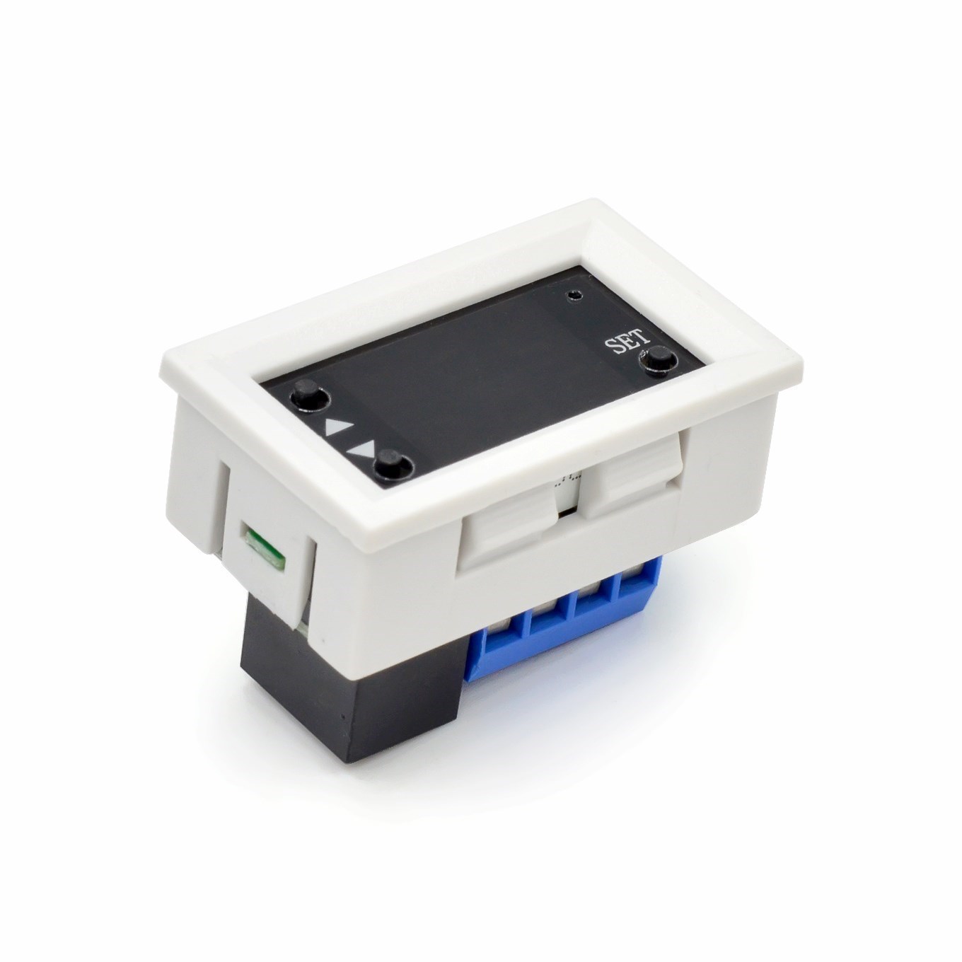
The 12V Digital Timer Relay Switch is a versatile, high-precision timing control module designed for automation systems, DIY electronics projects, and industrial applications. Operating on a standard 12V DC supply—compatible with automotive systems, solar battery banks, PLC panels, and other 12V DC power sources—this controller enables programmable time-based switching of electrical loads with exceptional accuracy and flexibility.
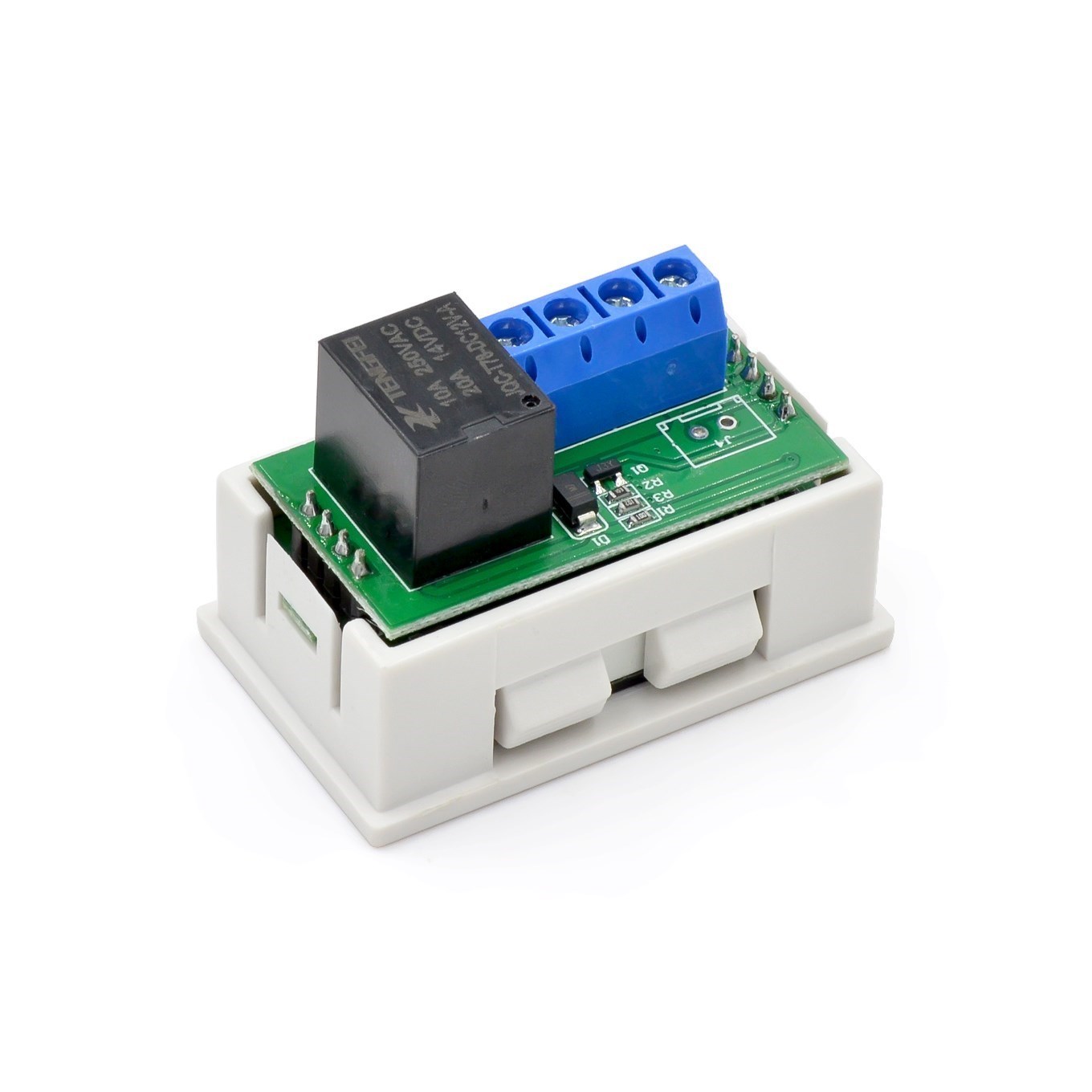
At the heart of this module is a powerful SPDT relay rated for up to 20A at 12V DC or 10A at 250V AC, allowing direct control of pumps, fans, lights, heaters, solenoids, and other equipment without requiring external contactors for moderate loads. The dual LED display (typically red and blue digits) shows both current timing parameters simultaneously, providing clear, real-time feedback during programming and operation .
The controller features multiple programmable timing modes (typically 12-18 modes depending on the specific model), including delay-on, delay-off, cycle timing (endless loop), interval timing, and pulse output modes. The timing range is adjustable from 0.01 seconds up to 999 minutes or 999 hours, depending on the selected unit . Users can set independent ON and OFF durations for each channel, making this device ideal for applications requiring repetitive cycling or precise single-shot timing.
Programmable operating modes include:
-
Countdown (Delay) Mode: Relay activates after a preset delay when triggered.
-
Cycle (Loop) Mode: Relay continuously alternates between ON and OFF states at programmed intervals.
-
Infinite Cycle Mode: Supports continuous on/off loop switching with settable ON and OFF times independently .
-
Trigger Modes: Supports high-level (3.0V–24.0V), low-level (0.0V–0.2V), or switch/button triggering .
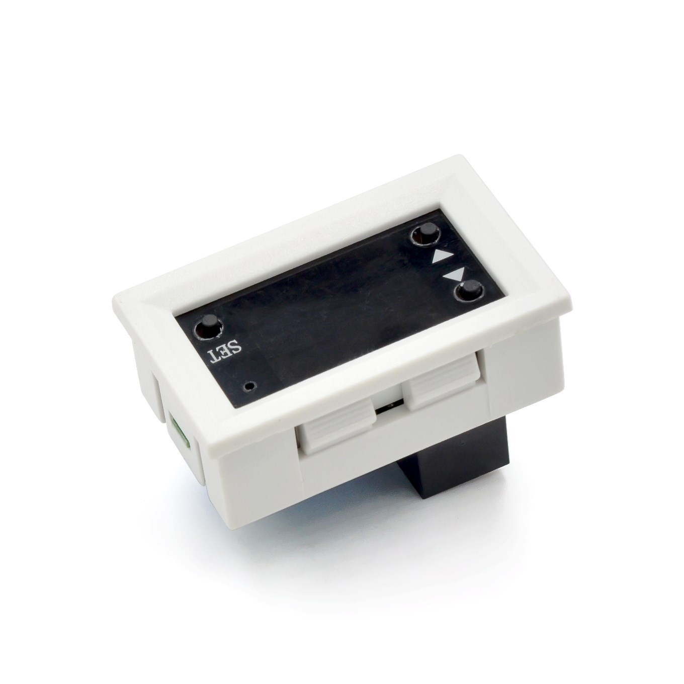
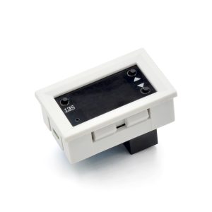
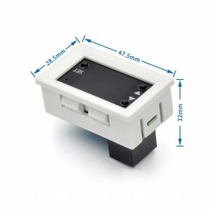
Additional features include a stop/pause button for emergency stopping, non-volatile memory that retains all settings after power loss, and an optocoupler-isolated input for enhanced noise immunity in industrial environments . The module is typically housed in a durable ABS plastic enclosure (or industrial-grade PCB with mounting holes) and can be panel-mounted or installed inside control cabinets.
Whether you need to automate a greenhouse irrigation system, create a timed ventilation fan for a workshop, control a 12V water pump on a timer, build a battery charger cycler, or program an industrial process timer, this 12V Digital Timer Relay Switch delivers reliable, accurate, and programmable timing control in a compact, easy-to-use package.
Key Features
-
Dual LED Display – Red and blue digital displays show real-time status and parameters simultaneously for easy monitoring .
-
Wide Timing Range – Adjustable from 0.01 seconds to 999 minutes (or 999 hours on advanced models) with selectable time units .
-
Multiple Operating Modes – Supports delay-on, delay-off, cycle (endless loop), interval, pulse, and trigger (high/low/switch) modes .
-
High-Current Relay Output – Rated for up to 20A at 12V DC or 10A at 250V AC (models vary; check specifications) .
-
12V DC Operation – Compatible with automotive systems, solar batteries, PLC panels, and 12V power supplies.
-
Optocoupler Isolation – Protects control circuitry from electrical noise and voltage spikes on trigger inputs .
-
Independent ON/OFF Timing – Set separate ON duration (OP) and OFF duration (CL) for cycle mode applications .
-
Non-Volatile Memory – All programmed parameters are automatically saved and retained after power loss .
-
Stop/Pause Function – Dedicated button provides emergency stop or pause capability during operation .
-
Panel/DIN Mountable – Compact design with mounting holes or DIN rail adapter compatibility for easy installation .
Technical Parameters
Usage Guide
How It Works
The controller monitors time based on user-programmed parameters. When the start condition is met (power applied or external trigger received), the controller begins counting according to the selected mode. Upon reaching the programmed time value(s), the relay changes state (ON to OFF or OFF to ON). The dual display shows the current status (e.g., “ON” or “OFF”) and the remaining time in the selected unit (seconds, minutes, or hours) .
Common Operating Modes
Note: Mode numbers and names may vary by specific model. Consult your product manual for exact mapping .
Wiring Instructions
Step 1 – Power Connection
Step 2 – Trigger/Sensor Connection (If Used)
Step 3 – Load Connection
Wiring Example – 12V DC Water Pump (Cycle Mode):
-
Connect 12V battery positive → COM terminal
-
Connect pump positive → NO terminal
-
Connect pump negative → battery negative directly
-
Program ON time (e.g., 30 seconds) and OFF time (e.g., 2 minutes)
-
Pump will automatically cycle on/off
⚠️ Safety Warning: High voltage (110V/220V AC) is dangerous. Disconnect all power before wiring. Use appropriately gauged wire for your load current (minimum 14 AWG for 10A, 12 AWG for 20A). Mount the controller in an enclosure for permanent installations.
Programming Instructions (Typical)
Basic Setup (Example based on XY-WJ01/T3230 series):
-
Power ON – The display will show current status.
-
Enter Menu – Press and hold the SET button for 3 seconds.
-
Select Mode (P0–P9) – Use UP/DOWN buttons to cycle through operating modes .
-
Set Time Unit – Choose seconds (SEC), minutes (MIN), or hours (HOUR).
-
Set OP Time (ON Duration) – Use UP/DOWN to adjust value; press SET to confirm.
-
Set CL Time (OFF Duration) – Use UP/DOWN to adjust value; press SET to confirm.
-
Set Cycles (LOP) – For cycle modes, set number of repetitions (1–999 or “—” for infinite) .
-
Save & Exit – Wait 6 seconds or long-press SET to save all settings to memory .
Time Setting Range:
Parameter Definitions:
-
OP (ON Period) : Duration the relay remains activated when triggered
-
CL (OFF Period) : Duration the relay remains deactivated in cycle modes
-
LOP (Loop Count) : Number of complete ON/OFF cycles to perform before stopping (“—” = infinite loop)
Installation Tips
-
Mounting: Secure using the four mounting holes (typically 3.1mm diameter) with M3 screws or use double-sided tape. For DIN rail mounting, use an optional adapter bracket .
-
Ventilation: Allow adequate airflow around the module, especially when switching high currents continuously.
-
Wire Gauge: Use 14–22 AWG wire for load connections depending on current. For 20A loads, minimum 12 AWG copper wire is recommended.
-
Enclosure: For permanent installations, mount the controller inside an electrical enclosure with appropriate strain relief.
-
Trigger Wiring: For long trigger cable runs (over 2 meters), use shielded cable to prevent false triggering from electrical noise.
Q: What operating modes are available on this timer relay?
Depending on the specific model (T3230, XY-WJ01, or T2310), the module typically supports 9–18 programmable modes including delay-on, delay-off, cycle (endless loop), interval, pulse, and various trigger response modes (high/low/switch, retriggerable, one-shot, etc.) . The most common modes are P0 (delay-on), P4 (cycle starting ON), P5 (cycle starting OFF), and P6 (infinite cycle).
Q: What is the difference between OP, CL, and LOP parameters?
-
OP (ON Period) : The duration the relay remains activated (closed) when timing conditions are met .
-
CL (OFF Period) : The duration the relay remains deactivated (open) in cycle modes .
-
LOP (Loop Count) : The number of complete OP+CL cycles to perform before stopping. Set to “—” for infinite continuous cycling .
Q: Can I use this timer with a 12V car battery?
Yes. The module is designed for 12V DC operation and works perfectly with automotive electrical systems (10.8V–13.2V). The standby current is very low (approximately 15mA), so it will not significantly drain your battery when not in use . However, if you plan to leave it connected for extended periods without driving, consider using a battery maintainer.
Q: What is the maximum load I can control with this relay?
The relay rating depends on the specific model:
-
T3230: 20A maximum (1500W at 12V DC)
-
T2310: 20A maximum (240W at 12V DC)
-
XY-WJ01: 10A maximum (5A at 220V AC)
For inductive loads (motors, pumps, solenoids, compressors), derate the relay rating by approximately 50% to account for inrush current and back EMF. For large inductive loads, use this relay to drive an external contactor.
Q: Can I use this controller for both home and business applications?
Home users: Aquarium light timers, hydroponic pump cyclers, reptile habitat day/night cycles, workshop ventilation fans, battery charger timers, holiday light displays, DIY sous vide controllers, garage door automation, pet feeder timers.
Business users: Greenhouse irrigation timing, industrial process timers, conveyor belt cycling, packaging machine controls, HVAC system scheduling, laboratory equipment timing, printing press interval control, food processing equipment timers, water treatment system cycling.
Q: Does the timer remember settings after a power outage?
Yes. The module features non-volatile EEPROM memory. All programmed parameters (operating mode, OP time, CL time, LOP cycles, time units) are automatically saved and retained indefinitely after power loss . When power is restored, the timer resumes operation with the saved settings.
Q: How accurate is the timing?
The timer uses a crystal oscillator or precision RC timing circuit with accuracy typically within ±1% to ±2% of the set value over normal temperature ranges. For long-duration timers (hours), drift is minimal. For applications requiring extreme precision (sub-millisecond), consider a dedicated precision timer module.
Q: What is the difference between the T3230, T2310, and XY-WJ01 models?
Your specific product may vary. Check the model number on the device or packaging for exact specifications.
Q: Can I use an external switch or sensor to trigger the timer?
Yes. The timer supports multiple trigger types:
-
High level (3.0V–24.0V) : Apply a positive voltage to trigger .
-
Low level (0.0V–0.2V) : Short the trigger pin to ground .
-
Switch/dry contact : Connect a push-button between IN and GND .
This makes it compatible with PIR motion sensors, float switches, limit switches, push buttons, and microcontroller outputs (Arduino, Raspberry Pi, etc.).
Q: What is the purpose of the STOP/PAUSE button?
The dedicated stop/pause button provides:
-
Emergency stop : Immediately deactivates the relay and halts timing .
-
Pause function : In cycle modes, pressing STOP pauses the current timing cycle; pressing again (or a trigger) resumes.
-
Reset function : In some modes, holding STOP resets the timer to idle state.
The display will flash “OUT” or similar indicator when paused .