L9110 L9110S DC Stepper Motor Driver Board Hbridge

SKU: FA2114
Chip Type

L9110S (Dual H-Bridge)

Number of Channels

2 (Independent)

Operating Voltage (VCC)

DC 2.5V – 12V

Continuous Output Current (Per Channel)

800mA

Peak Output Current (Per Channel)

2A

Control Signals

TTL Level (3.3V/5V Compatible)

Speed Control Method

PWM (Pulse Width Modulation)

Logic Input Level

High: 2.5V – 5V, Low: 0V – 0.5V

Board Dimensions

29mm × 21mm × 5mm

Mounting Hole Diameter

3mm

Weight

Approx. 5g – 10g

Product Overview

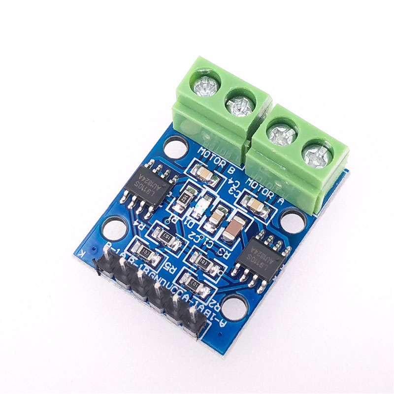
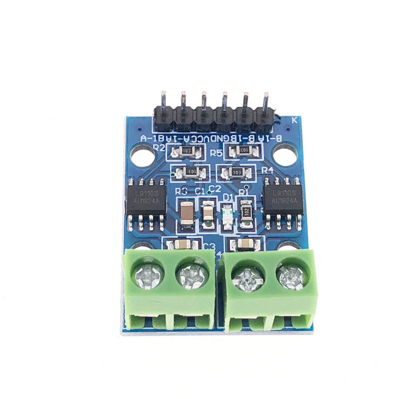
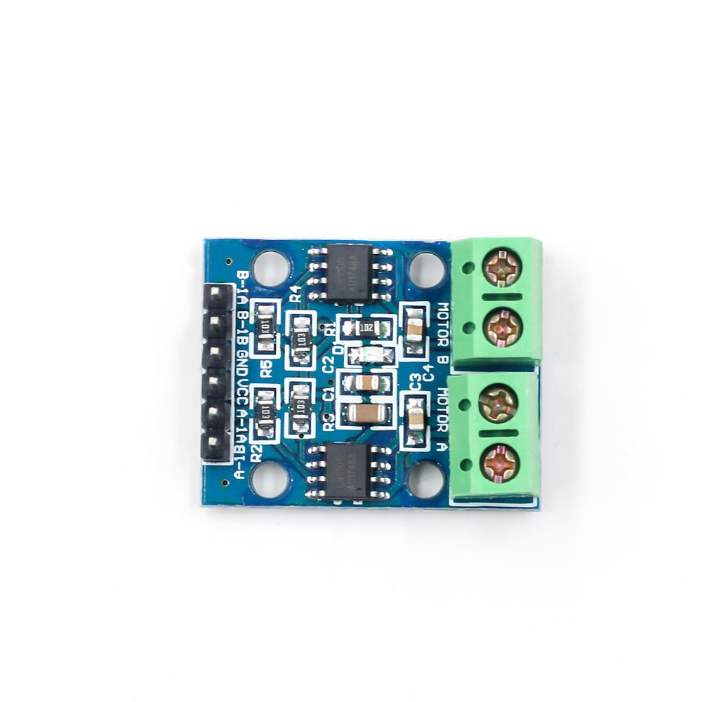
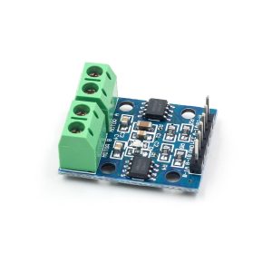
The L9110S Dual-Channel Motor Driver Board is a compact, high-efficiency H-bridge driver module designed for controlling small DC motors or a single 4-wire bipolar stepper motor . Built around the L9110S motor driver IC, this board integrates two independent H-bridge circuits, allowing you to control the speed and direction of two DC motors simultaneously or drive one stepper motor with precision .

This module is a favorite among hobbyists and professionals for smart car projects, DIY robots, and automation systems . It offers a simple control interface: you use standard PWM (Pulse Width Modulation) signals for speed control and standard digital outputs (High/Low) to change the motor’s direction . The control logic is straightforward, with all critical signal pins broken out to easy-to-use 2.54mm headers.

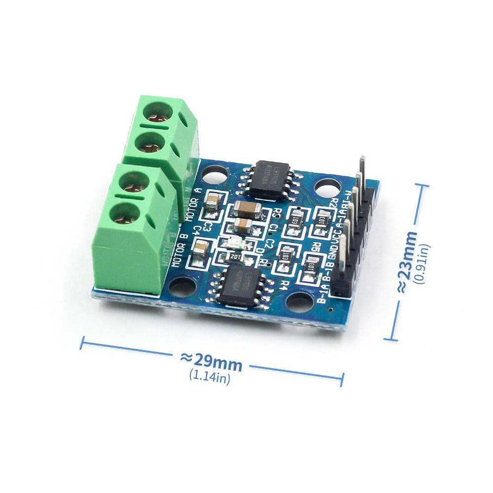
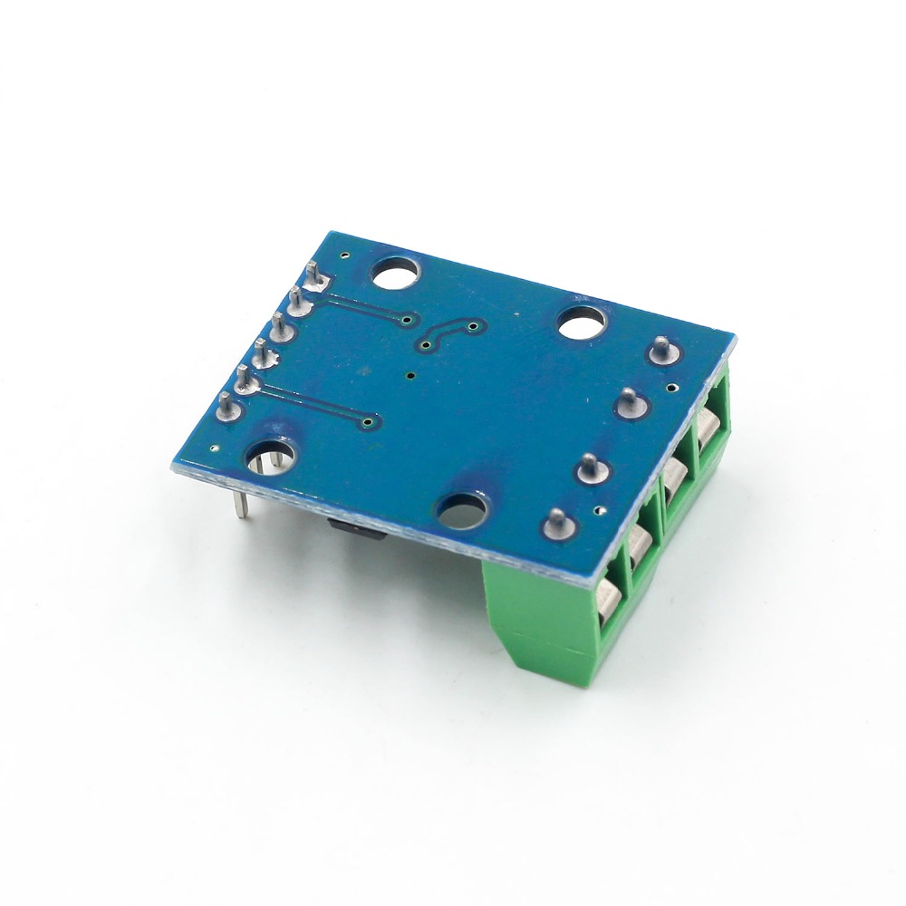
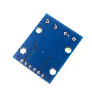
One of the biggest advantages of the L9110S is its miniaturized size. The board measures approximately 29mm x 21mm, making it ideal for portable and space-constrained applications . Despite its small footprint, it features built-in flyback diodes for protection against motor-induced voltage spikes, ensuring the stability and longevity of your main control circuit . Whether you are building a line-follower robot or a wireless smart car, the L9110S provides the essential drive power you need.

Key Features

  • Dual Channel H-Bridge: Two independent H-bridge channels that can control two DC motors (bi-directional) or one 4-wire stepper motor simultaneously.

  • Wide Power Supply Voltage: Wide operating voltage range of 2.5V to 12V, supporting both 3.3V and 5V logic systems.

  • High Current Output: Each channel supports a continuous current of up to 800mA, with a peak current capability of up to 2A.

  • PWM & Direction Control: Supports PWM for smooth speed regulation and digital logic for motor direction control.

  • Compact Size: Extremely small board dimension of 29mm × 21mm, fitting perfectly into small robotic chassis.

  • Built-in Protection: Onboard flyback diodes absorb reverse currents generated by the motor, protecting the IC from damage.

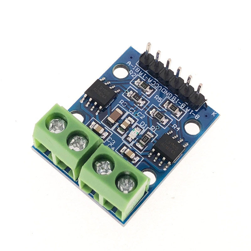
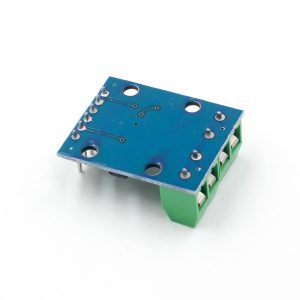
  • Simple Pin Interface: 4 control pins (A-IA, A-IB, B-IA, B-IB) and 4 motor output terminals (Motor A/B).

  • Dual Power Input: Separate power lines for the logic chip (VCC) and the motor power supply, reducing interference.

  • Mounting Holes: Includes 4 mounting holes (3mm diameter) for easy installation onto robot frames or enclosures.

  • Wide Compatibility: Perfect for use with Arduino UNO, Nano, Mega, ESP32, and STM32 development boards.

Technical Specifications

Parameter Operating Value
Chip Type L9110S (Dual H-Bridge)
Number of Channels 2 (Independent)
Operating Voltage (VCC) DC 2.5V – 12V
Continuous Output Current (Per Channel) 800mA
Peak Output Current (Per Channel) 2A
Control Signals TTL Level (3.3V/5V Compatible)
Speed Control Method PWM (Pulse Width Modulation)
Logic Input Level High: 2.5V – 5V, Low: 0V – 0.5V
Board Dimensions 29mm × 21mm × 5mm
Mounting Hole Diameter 3mm
Weight Approx. 5g – 10g

Pinout & Interface Guide

The control of the L9110S is extremely simple. The module’s pinout is clearly labeled for easy wiring.

Control Pins (Connect to Microcontroller)

Pin Symbol Label on PCB Description
VCC VCC / + Connect to the motor power supply (2.5V – 12V).
GND GND / – Connect to the common ground of the microcontroller and power battery.
A-IA (IN1) A-IA / IN1 Control signal input for Motor A.
A-IB (IN2) A-IB / IN2 Control signal input for Motor A.
B-IA (IN3) B-IA / IN3 Control signal input for Motor B.
B-IB (IN4) B-IB / IN4 Control signal input for Motor B.

*Note: Some boards label the pins as IA/B, and others as IN1-4 .*

Motor Output Terminals

Terminal Description
Motor A Outputs (OUTA1/OUTA2) Connect the two wires of DC Motor A here.
Motor B Outputs (OUTB1/OUTB2) Connect the two wires of DC Motor B here.

Truth Table (Motor A Control)

A-IA (IN1) A-IB (IN2) Motor A State
PWM (Speed Signal) LOW Forward (Speed = PWM Duty Cycle)
LOW PWM (Speed Signal) Reverse (Speed = PWM Duty Cycle)
LOW LOW Coast / Stop (Free-run stop)
HIGH HIGH Brake / Stop (Instant stop)

(The same logic applies to Motor B, using pins B-IA and B-IB.)

Usage Guide

Hardware Wiring

  1. Connect Power: Connect the Motor Power supply (2.5V – 12V) to the VCC and GND terminals. Note: Do not power the motor directly through the Arduino’s 5V pin to avoid voltage drop..

  2. Connect Motors: Connect the two wires of Motor A to the Motor A Output terminals (OUTA1/OUTA2). Connect Motor B similarly.

  3. Connect to Microcontroller:

    • Connect GND of the L9110S to GND of the microcontroller. This is mandatory for stable operation .

    • Connect A-IA (IN1) to Arduino digital pin 5.

    • Connect A-IB (IN2) to Arduino digital pin 6.

    • Connect B-IA (IN3) to Arduino digital pin 9.

    • Connect B-IB (IN4) to Arduino digital pin 10.

Basic Arduino Code Example

This sketch demonstrates controlling Motor A with Forward/Reverse speed cycles.

cpp
// L9110S Motor Driver Control Example
// Motor A: IA -> Pin 5, IB -> Pin 6

int IA = 5;  // Speed/Direction pin
int IB = 6;  // Direction/Speed pin

void setup() {
  pinMode(IA, OUTPUT);
  pinMode(IB, OUTPUT);
  Serial.begin(9600);
}

void loop() {
  // Motor Forward at 70% Speed
  analogWrite(IA, 178);   // PWM Speed to IA
  digitalWrite(IB, LOW);  // IB LOW for Forward direction
  delay(3000);

  // Motor Stop (Coast)
  digitalWrite(IA, LOW);
  digitalWrite(IB, LOW);
  delay(2000);

  // Motor Reverse at 50% Speed
  digitalWrite(IA, LOW);          // IA LOW for Reverse direction
  analogWrite(IB, 127);            // PWM Speed to IB
  delay(3000);

  // Motor Brake
  digitalWrite(IA, HIGH);
  digitalWrite(IB, HIGH);
  delay(2000);
}
Q: What is the maximum voltage and current for this L9110S module?

The recommended operating voltage range is 2.5V to 12V DC . The maximum continuous output current per channel is approximately 800mA (Peak up to 2A) .

Q: The motor runs very slowly or not at all. What's wrong?

This is usually a power supply issue. Ensure your battery voltage matches the motor’s requirement. The most common mistake is forgetting to connect the GND of the microcontroller board to the GND of the L9110S driver board . A weak battery cannot supply the surge current required to start the motor.

Q: How do I control the speed of the motor?

You must use Pulse Width Modulation (PWM). Send a PWM signal to the IA pin (for Motor A) while holding the IB pin LOW to achieve forward speed control . To reverse, send PWM to IB while holding IA LOW.

Q: Can I run a stepper motor with this L9110S module?

Yes. This module can drive a 4-wire bipolar stepper motor. Connect one coil to the OUTA terminals and the other coil to the OUTB terminals, then follow the standard 8-bit or half-step stepping sequence in your code .

Q: Does the L9110S have overcurrent or short circuit protection?

The chip has basic thermal shutdown (over-temperature) protection to prevent the IC from overheating during a stall or overload, but its primary protection is the internal flyback diode against inductive surges . It does not feature a dedicated current sense or software-adjustable current limit.

Q: Is there a difference between the L9110 and L9110S?

Both are nearly identical. The “S” typically stands for the surface-mount package version of the chip (SOIC vs DIP). In practice, the “L9110S” has become the standard name for the chip used on these small breakout boards, offering the same specs (800mA, 12V max).