Product Overview
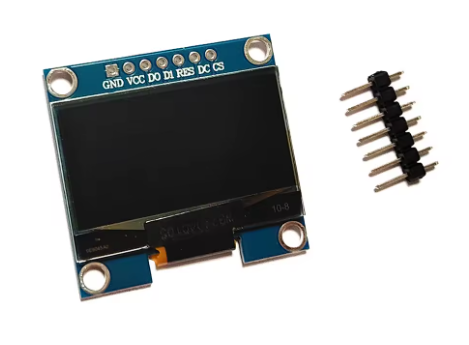
The 1.3-inch Blue 7-Pin OLED Display Module is a high-contrast monochrome graphic display designed for embedded applications. Powered by the SH1106 driver IC with a sharp 128×64 pixel resolution, this 7-pin variant offers the highest flexibility, supporting both SPI and I2C communication protocols. The default configuration is 4-wire SPI, which provides faster data transfer compared to I2C, making it ideal for animations, real-time sensor dashboards, and dynamic user interfaces.
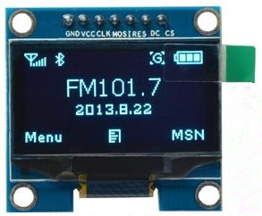
OLED (Organic Light Emitting Diode) technology requires no backlight, as each pixel emits its own light. This self-emissive design delivers true blacks (inactive pixels are completely off), exceptional contrast, and >160° viewing angles . The bright blue monochrome display ensures excellent readability in all lighting conditions while consuming minimal power for battery-operated projects.
The module includes a dedicated Chip Select (CS) pin, allowing multiple SPI devices to share the same bus without conflicts—essential for complex projects with multiple peripherals. With support for both 3.3V and 5.5V power supply, it works with Arduino (using level shifters for logic pins), ESP32, STM32, and Raspberry Pi .
Key Features
-
1.3-Inch Active Area: 29.4mm × 14.7mm display area offers 110 DPI pixel density for sharp text and graphics
-
128×64 Pixel Resolution: High-definition display capable of showing detailed graphics, bitmaps, custom icons, and up to 8-16 lines of text
-
Blue Monochrome OLED: Vibrant blue pixels on true black background provide excellent contrast and professional appearance
-
SH1106 Driver IC: Industry-standard controller with built-in 132×64-bit SRAM buffer; supports SPI and I2C modes
-
7-Pin SPI Interface: Full SPI interface with dedicated CS (Chip Select) pin for multi-device bus sharing
-
Independent Control Pins: RES (Reset), DC (Data/Command), and CS (Chip Select) pins for full display control
-
Wide Voltage Compatibility: Accepts 3.3V–5.5V power supply (VCC); compatible with both 5V and 3.3V systems
-
⚠️ Logic Level Warning: SPI logic pins are 3.3V only – must use level shifters with 5V microcontrollers
-
Industrial Temperature Range: Rated for -40°C to +70°C, suitable for demanding environments
-
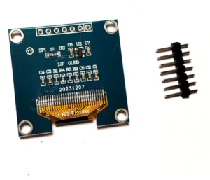
SPI/I2C Switchable: Supports both SPI (default) and I2C protocols via resistor configuration on the back of PCB
Technical Specifications
Pinout & Connection Guide
Pin Definitions (7-Pin SPI, Counter-Clockwise Orientation)
Connection Diagram (ESP32 – Direct Connection, No Level Shifters Needed)
ESP32 operates at 3.3V logic, matching the display’s logic requirements – connect directly:
Connection to Arduino Uno (5V) – Level Shifters Required
⚠️ CRITICAL: The logic pins (D0, D1, RES, DC, CS) are NOT 5V tolerant . You MUST use 3.3V logic level shifters. The VCC power pin IS 5V tolerant and can connect directly to 5V.
Alternative: Use a 3.3V board (ESP32, Arduino Pro Mini 3.3V, Raspberry Pi) to avoid level shifters entirely.
SPI vs I2C Mode Comparison
The 7-pin module supports both SPI and I2C protocols. The default configuration is 4-wire SPI .
Usage Guide
Software Setup (Arduino IDE)
Step 1: Install the U8g2 Library
The U8g2 library by Oliver Kraus is the most reliable choice for SH1106 displays, offering excellent support and many font options.
-
Open Arduino IDE → Sketch → Include Library → Manage Libraries
-
Search for “U8g2” by Oliver Kraus
-
Click Install
Step 2: Basic Test Sketch (Hardware SPI Mode)
For ESP32 / 3.3V microcontrollers (direct connection):
#include <Arduino.h>
#include <U8g2lib.h>
#include <SPI.h>
U8G2_SH1106_128X64_NONAME_1_4W_HW_SPI u8g2(U8G2_R0, 5, 2, 4);
void setup() {
u8g2.begin();
u8g2.enableUTF8Print();
u8g2.setFont(u8g2_font_ncenB08_tr);
u8g2.setDrawColor(1);
}
void loop() {
u8g2.firstPage();
do {
u8g2.drawStr(0, 15, "1.3 OLED");
u8g2.drawStr(0, 35, "128x64");
u8g2.drawStr(0, 55, "SPI 7-Pin");
} while ( u8g2.nextPage() );
delay(1000);
}
Step 3: Software SPI Mode (Any Pins)
If you prefer not to use hardware SPI pins:
#include <Arduino.h>
#include <U8g2lib.h>
U8G2_SH1106_128X64_NONAME_1_4W_SW_SPI u8g2(U8G2_R0, 13, 11, 10, 9, 8);
void setup() {
u8g2.begin();
u8g2.setFont(u8g2_font_ncenB08_tr);
}
void loop() {
u8g2.firstPage();
do {
u8g2.drawStr(0, 20, "Hello SH1106!");
} while ( u8g2.nextPage() );
delay(1000);
}
Step 4: I2C Mode Connection (After Resistor Modification)
If you modify the resistors to enable I2C mode :
-
Remove jumper on BS1 (set to 0)
-
Configure resistors accordingly
-
Connect only 4 pins: VCC, GND, SCL, SDA
I2C Arduino Example Code:
#include <Arduino.h>
#include <U8g2lib.h>
#include <Wire.h>

U8G2_SH1106_128X64_NONAME_F_HW_I2C u8g2(U8G2_R0, U8X8_PIN_NONE);

void setup() {
  u8g2.begin();
  u8g2.setFont(u8g2_font_ncenB08_tr);
}

void loop() {
  u8g2.firstPage();
  do {
    u8g2.drawStr(0, 20, "I2C Mode");
  } while ( u8g2.nextPage() );
  delay(1000);
}
Raspberry Pi Setup (Python)
-
Enable SPI: sudo raspi-config → Interface Options → SPI → Yes
-
Install required libraries:
sudo apt-get install python3-pip
pip3 install luma.oled
-
Python example code:
from luma.core.interface.serial import spi
from luma.oled.device import sh1106
from luma.core.render import canvas
serial = spi(port=0, device=0, gpio_DC=24, gpio_RST=25, gpio_CS=8)
device = sh1106(serial)
with canvas(device) as draw:
draw.rectangle(device.bounding_box, outline="white", fill="black")
draw.text((30, 20), "1.3 OLED", fill="white")
draw.text((30, 40), "SPI 128x64", fill="white")
Understanding the Display Buffer Workflow (U8g2)
U8g2 uses a page-buffered approach to manage memory:
u8g2.firstPage();
do {
u8g2.drawStr(0, 20, "Hello");
} while ( u8g2.nextPage() );
This structure allows the same code to work on both full-buffer and low-memory devices .
SH1106 vs SSD1306 Important Note
The SH1106 driver has internal RAM of 132×64 pixels, while the visible area is 128×64 pixels. The column start address for SH1106 is 0x02, unlike SSD1306 which uses 0x00 . Most modern libraries (U8g2, Adafruit_SH110X) handle this automatically.
Power Management for Battery-Powered Projects
Only lit pixels consume power, making OLEDs excellent for battery-powered applications:
Q: What is the advantage of the 7-pin version over the 4-pin I2C version?
The 7-pin version offers full SPI interface with a dedicated Chip Select (CS) pin. SPI is significantly faster than I2C (up to 10MHz vs 400kHz), making it ideal for animations, real-time data dashboards, and high refresh rate applications. The dedicated CS also allows multiple SPI devices to share the same bus .
Q: Can I use this display with a 5V Arduino Uno directly?
NO! The logic pins (D0, D1, RES, DC, CS) are NOT 5V tolerant . You MUST use 3.3V logic level shifters on all these pins. However, the VCC power pin IS 5V tolerant and can connect directly to 5V. For beginners, using a 3.3V board (ESP32, Raspberry Pi) is strongly recommended to avoid level shifters.
Q: What is the difference between SH1106 and SSD1306 drivers?
The SH1106 has internal RAM of 132×64 pixels, while the visible area is 128×64 pixels. This means SH1106 requires a column start address of 0x02, while SSD1306 uses 0x00 . Most modern libraries (U8g2, Adafruit) handle this automatically, but older libraries may require configuration changes for SH1106.
Q: Why does my display stay blank after power-up?
Common issues to check:
-
Logic voltage mismatch – if using 5V Arduino, did you use level shifters?
-
Wiring – verify VCC and GND connections
-
Library initialization – ensure you selected the SH1106 driver in U8g2
-
SPI pins – verify CLK and MOSI are connected to correct hardware SPI pins
-
CS pin connection – ensure CS is properly connected or held LOW
-
Reset sequence – power-on reset pulse may be needed
Q: Can I switch this display to I2C mode?
Yes. The module supports both SPI and I2C by configuring resistors on the back of the PCB. Modify BS1 and BS2 pins accordingly . In I2C mode, the DC pin must be connected to power (3.3V or 5V) and the address is typically 0x3C .
Q: How do I use multiple SPI devices with this display?
The dedicated CS (Chip Select) pin allows multiple SPI devices on the same bus. Connect all devices’ CLK and MOSI pins together, but give each device a unique CS pin. Set the CS pin LOW only for the device you’re communicating with; set others HIGH .
Q: How many characters can the display show?
With the default 8×8 pixel font, approximately 16 characters × 8 lines = 128 characters total. With larger fonts (e.g., 16×16 pixels), about 8 characters × 4 lines = 32 characters. The 128×64 resolution provides excellent clarity for both text and graphics.
Q: Can I display custom bitmap images on this OLED?
Yes. Use tools like LCD Image Converter, Image2CPP, or online converters to transform 128×64 monochrome bitmap images into C arrays. In U8g2, use u8g2.drawXBM(x, y, width, height, bitmap_data) to display images.
Q: What is the lifespan of the OLED display?
Rated lifespan is approximately 20,000-30,000 hours of continuous operation (about 2.5-3.5 years). Avoid displaying static images for extremely long periods to prevent uneven pixel wear (commonly known as “burn-in”). For typical intermittent hobbyist use, this is not a concern.
Q: Does this module have pull-up resistors for SPI mode?
No. SPI mode does not require pull-up resistors on CLK/MOSI lines. Leave them unconnected or use standard 4.7k-10kΩ resistors if noise is an issue. In I2C mode, pull-up resistors are required on SDA and SCL lines (typically 4.7kΩ to VCC). Most modules include onboard pull-ups for I2C .