Product Overview
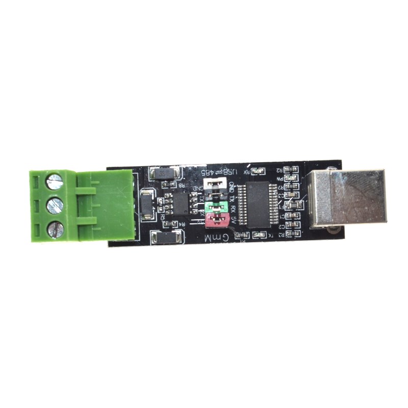
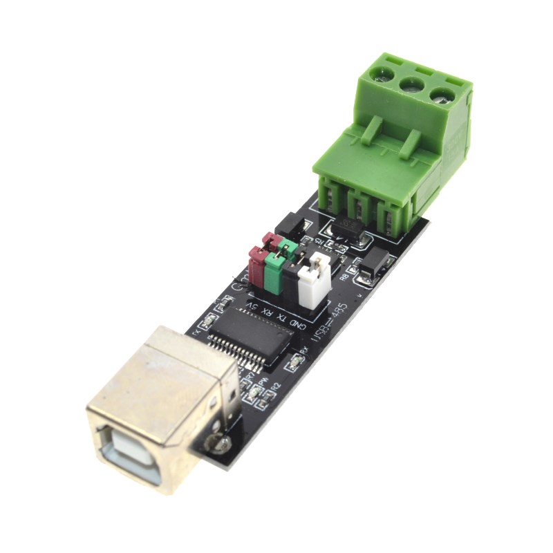
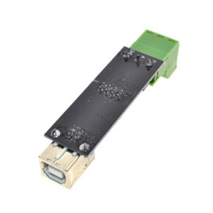
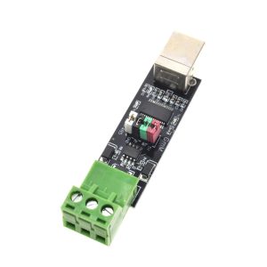
The USB to RS485 TTL Serial Converter Adapter based on the FT232 chip is a professional-grade interface converter that bridges the gap between a computer’s USB port and RS485 industrial communication networks. Built around the authentic FTDI FT232 series chipset (options include FT232RL, FT232RNL, or FT232HL), this converter provides a reliable, high-performance solution for connecting modern computers to RS485-based devices commonly found in industrial automation, building management systems, and data acquisition networks .
Unlike simple USB-to-TTL adapters, this converter handles the complete protocol conversion from USB to RS485 differential signaling, enabling long-distance communication (up to 1200 meters) and multi-device networking . The onboard FT232 chip handles the USB protocol stack and provides a virtual COM port on your computer, while the RS485 transceiver converts the TTL-level UART signals to the differential RS485 standard (A and B lines) . The FT232 series supports standard baud rates up to 921600 bps and features a dedicated TXDEN (Transmit Enable) pin for automatic RS485 driver direction control—eliminating the need for software handshaking and reducing CPU overhead .
This converter is an essential tool for PLC communication, Modbus RTU networking, industrial sensor data logging, building automation systems, solar inverter monitoring, and interfacing with legacy RS485 equipment. Its compact, rugged design (often housed in an industrial-grade metal case) and built-in protection circuits make it ideal for both field service and permanent installation .
Key Features
-
Original FTDI FT232 Chipset: Powered by authentic FTDI FT232 series (RL/RNL/HL) chips for superior driver stability, broad OS compatibility, and reliable high-speed communication .
-
RS485 Differential Signaling: Converts USB to RS485 (half-duplex) using a robust transceiver (such as MAX485/SP481), supporting long-distance communication up to 1200 meters and multi-point networking .
-
Automatic Direction Control: Utilizes the FT232’s dedicated TXDEN (Transmit Enable) pin to automatically enable the RS485 driver during transmission, with zero software delay—no manual RTS/CTS control required .
-
High-Speed Data Transfer: Supports baud rates from 300 bps up to 2 Mbps (up to 921600 bps for RS232), suitable for high-speed industrial data logging and real-time control .
-
Comprehensive Protection Circuits: Onboard TVS diodes (Transient Voltage Suppressor), self-recovery fuse (typically 200mA), and protection diodes guard against ESD, surge voltages, over-current, and reverse polarity .
-
Industrial Design Options: Available in aluminum alloy cases (for superior EMI/RFI shielding) or enclosed modules with cooling vents. Some models feature DIN rail mounting or wall-mount brackets for permanent installation .
-
Status Indicator LEDs: Dedicated LED indicators for Power (PWR), Transmit (TXD), and Receive (RXD) provide clear visual feedback of communication status .
-
Wide Power Supply Compatibility: Operates via USB bus power (5V) or external 5V supply. Some industrial isolated versions require no external power for the RS485 side due to onboard DC-DC isolation .
-
Cross-Platform Driver Support: FTDI virtual COM port (VCP) drivers are built into Windows, macOS (10.9+), Linux kernels (2.6+), and Android, ensuring true plug-and-play operation .
Technical Specifications
Pinout & Connection Guide
This converter typically uses a screw terminal block for connecting to your RS485 network.
RS485 Terminal Block
Wiring Rules for RS485 Networks :
-
Connection: Connect the A terminal of all devices together and the B terminal of all devices together.
-
Grounding: For long distances ( > 100m) or electrically noisy environments, connect the GND terminals of all devices to establish a common reference voltage.
-
Termination: To prevent signal reflections, place a 120Ω resistor between the A and B terminals at the two farthest ends of the cable .
-
Cable Type: Use twisted-pair shielded cable (CAT5e or dedicated RS485 cable) for best noise immunity.
Connection to a Single RS485 Device
Converter Terminal      Device Terminal
    A+      ───────────      A+ / RX+ / D+
    B-      ───────────      B- / RX- / D-
    GND     ───────────      GND (if available)
Connection to a Multi-Drop Network (e.g., Modbus RTU)
-
Connect A to A across all devices (Master and Slaves).
-
Connect B to B across all devices.
-
Place 120Ω termination resistors at the physical ends of the cable only.
-
Connect Grounds in a star or daisy-chain configuration for noise reduction.
Usage Guide
1. Driver Installation
The FT232 chip requires Virtual COM Port (VCP) drivers. FTDI drivers are standard in most modern operating systems . If the device is not recognized automatically, download the latest drivers from the official FTDI Chip website.
-
Windows: Driver installation is automatic via Windows Update on most systems. Manual driver (CDM) available for legacy OS from FTDI.
-
macOS: Included in the OS (10.9 and later)
-
Linux: Built-in to the kernel (ftdi_sio module)
-
Android: Supported via USB Host mode and external drivers.
Verification:
2. Basic Communication Test
Once the driver is installed, the converter operates as a standard COM port. You can test it using any serial terminal software (e.g., Putty, CoolTerm, Arduino Serial Monitor).
-
Connect the A and B terminals together (loopback test).
-
Open a serial terminal program.
-
Select the correct COM port and set the baud rate (e.g., 9600).
-
Type characters. In a loopback test, the characters you type will be echoed back to the screen.
3. Operating Principles (Why it works well with FTDI)
RS485 is half-duplex, meaning the line cannot transmit and receive simultaneously. The FT232’s TXDEN signal is the key to automatic hardware flow control .
-
Transmit Mode: When your software sends data to the COM port, the FT232 chip activates its TXDEN pin before the start bit is sent. This signal enables the RS485 driver (transmitter) and disables the receiver.
-
Receive Mode: When the transmission is complete, TXDEN is deactivated, the RS485 driver is tri-stated (disconnected), allowing other devices on the bus to transmit and enabling the converter’s receiver.
-
Result: You do not need to use the RTS pin or write special code to toggle the RS485 direction. The hardware handles this automatically, resulting in transparent communication .
4. Modbus RTU Protocol
This converter is ideal for Modbus RTU industrial networks . Modbus RTU is a widely used protocol that transmits binary data (8-bit bytes) over RS485. The FT232 converter handles the physical layer, while a software library (like pySerial or libmodbus) handles the Modbus framing and CRC checking.
5. Integration with Arduino / ESP32
While this is a USB converter, it can be used to add an RS485 port to a system. If you need an RS485 transceiver directly on a microcontroller board, use a TTL to RS485 module (e.g., MAX485). This USB converter is intended for connecting a PC to the RS485 bus as a master or monitoring device.
Q: What is the difference between this FT232 RS485 converter and a common USB-to-TTL adapter?
A standard USB-to-TTL adapter outputs 3.3V or 5V single-ended signals suitable for a few inches of wiring. This FT232 RS485 converter is specifically designed for long-distance industrial communication. It converts the TTL signals to differential RS485 (A/B lines), supports multi-drop networks (up to 32 devices), and is immune to electrical noise.
Q: Why are FTDI chips preferred over CH340 or CP2102 for RS485?
FTDI chips have a standard hardware feature called TXDEN (Transmit Enable) . This pin automatically enables the RS485 driver precisely when data is being transmitted and disables it afterward. For other chips (like CH340 or CP2102), you must manually control the RS485 direction via a GPIO pin (RTS), which requires complex driver-level modifications or special code. The FT232 solution is “zero-delay” and works transparently with standard serial COM port software.
Q: Do I need an external power supply for this converter?
For standard versions, No. The converter is bus-powered via USB (5V), which provides enough power for the FT232 chip and the RS485 transceiver. For industrial “isolated” versions, the isolation side is also powered by the USB 5V rail; no external power is needed . An external power supply is only required if you use a “passive” converter that lacks a USB power regulator.
Q: How do I know which COM port the converter is using?
-
Windows: Open Device Manager → Ports (COM & LPT). Look for “USB Serial Port (COMx)”. The number (COM3, COM5, etc.) is assigned by Windows.
-
Linux: Type dmesg | grep tty in a terminal after plugging in the device; you will see ttyUSB0 (or similar).
-
macOS: Check ls /dev/cu.usbserial-*.
Q: Can I change the COM port number on Windows?
Yes. You can reassign the PORT number (e.g., from COM5 to COM2) in Device Manager → Ports → Right-click the device → Properties → Port Settings → Advanced. Select a new COM port number from the dropdown list.
Q: Why is my Modbus communication failing or producing CRC errors?
-
Baud Rate & Settings: Ensure ALL devices on the bus (master and slaves) use exactly the same baud rate, data bits (8), parity (None/Even/Odd), and stop bits (1 or 2).
-
Termination: For long cables (>100m), you must have 120Ω termination resistors at both ends of the bus . Lack of termination causes signal reflections and data corruption.
-
Wiring Polarity: Verify that A is connected to A and B to B throughout the network. Swapping A and B on one device will cause that node to malfunction.
-
Unique Addressing: Each slave device on a Modbus RTU network must have a unique address (1-247).
Q: Can I connect this converter directly to an RS232 port?
This specific module is designed for RS485. RS232 uses different voltage levels (±3V to ±15V) and a different connector (DB9). Do not connect the A/B terminals to an RS232 port, as this could damage the converter. Use a dedicated RS232 converter if you need RS232.
Q: Does the FT232 converter work with Linux and macOS?
Yes. FTDI’s VCP drivers are built into the Linux kernel (via the ftdi_sio module) and macOS (10.9 and later). The converter is plug-and-play; no manual driver installation is required .
Q: How do I enable the 120Ω termination resistor?
Many converter modules have a jumper or a solder pad for the termination resistor .
-
Jumper: Place a jumper cap over the two pins labeled “120R” or “Term” to connect the 120Ω resistor between A and B.
-
Solder Pad: Solder a small blob across the designated pads to enable the resistor.
Enable termination only if this converter is physically located at one of the two ends of the network cable.
Q: What is the maximum number of devices I can connect?
The RS485 standard allows up to 32 “unit loads” on a single segment . Most modern transceivers are 1/8th unit load, allowing up to 256 devices. For large networks with more than 32 devices, you must use RS485 repeaters to isolate segments.