


DESCRIPTION
The IR Obstacle Avoidance Sensor Module uses an infrared emitter / receiver pair to detect obstacles in front of the sensor.
PACKAGE INCLUDES
- IR Obstacle Avoidance Sensor Module
KEY FEATURES OF IR OBSTACLE AVOIDANCE SENSOR MODULE
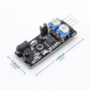
- Detection range from 2 cm to a maximum of 10 – 40 cm
- Uses HS0038B IR Receiver
- Oscillator frequency and duty cycle adjustment potentiometers
- 3.3 and 5V compatible
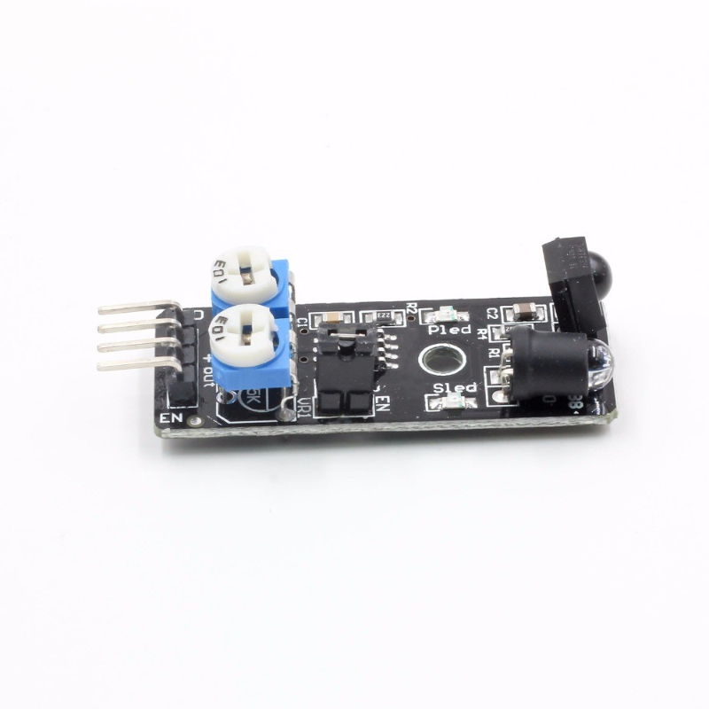
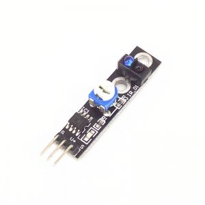
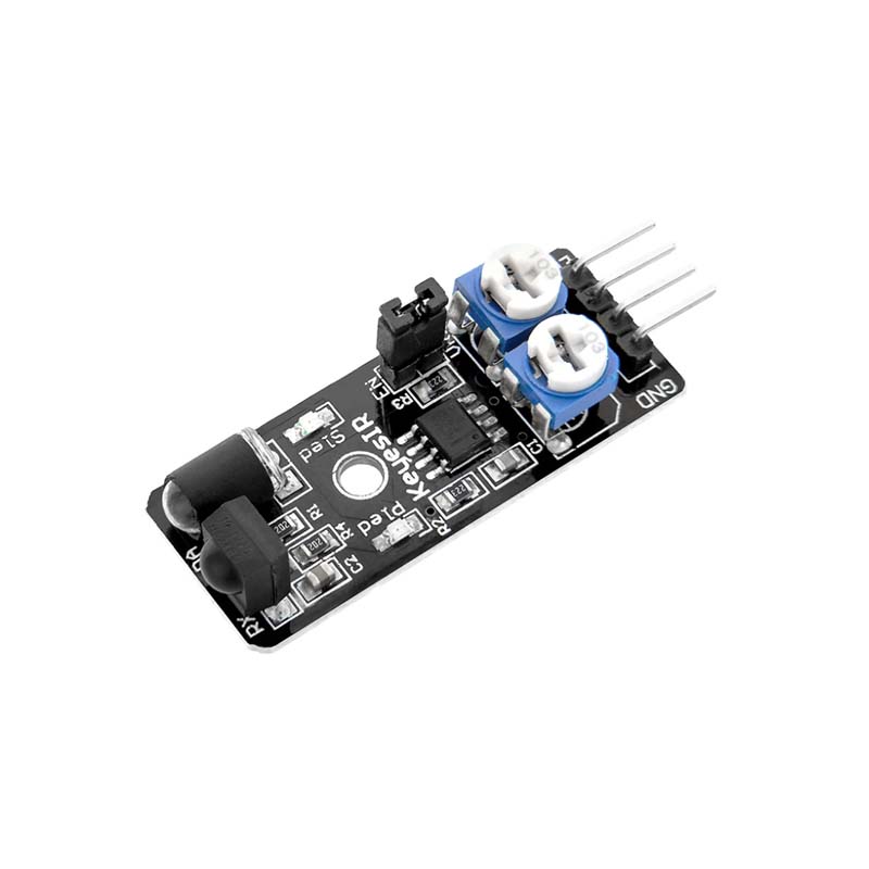
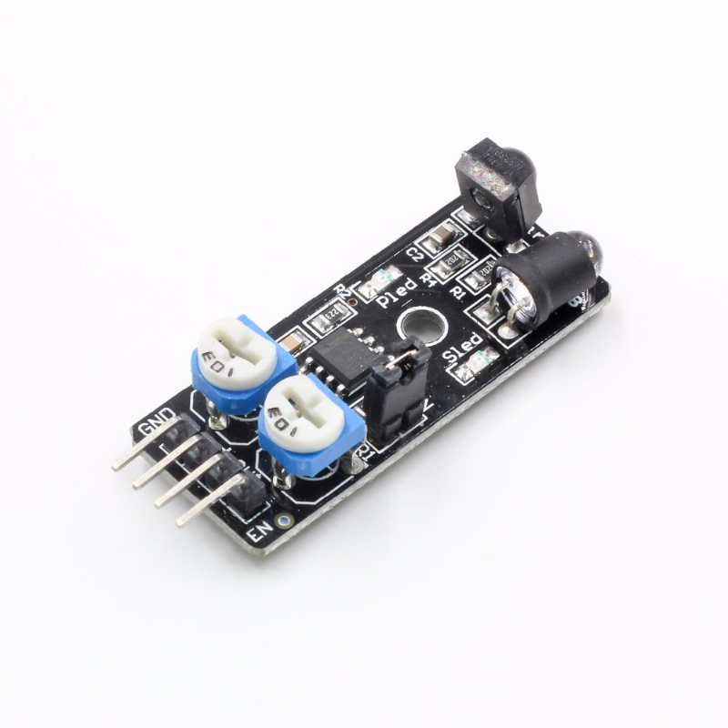
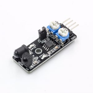
This IR Obstacle Avoidance Sensor uses an IR emitting LED and IR Receiver pair to detect obstacles in front of the sensor by the IR Receiver detecting the IR that is bounced of an object by the IR Emitter. Per specification, the device can detected objects in the range of 2 to 40 cm in front of it.
The clear LED is the IR emitter and the black device next to it is the HS0038B IR Receiver. The black case of the receiver helps to block light that is not in the IR spectrum. The device works by operating the IR LED at a frequency of 38KHz and detecting the IR energy from the LED which is bounced off an object and directed back at the IR Receiver module which is looking for an IR signal in the 38KHz frequency range.
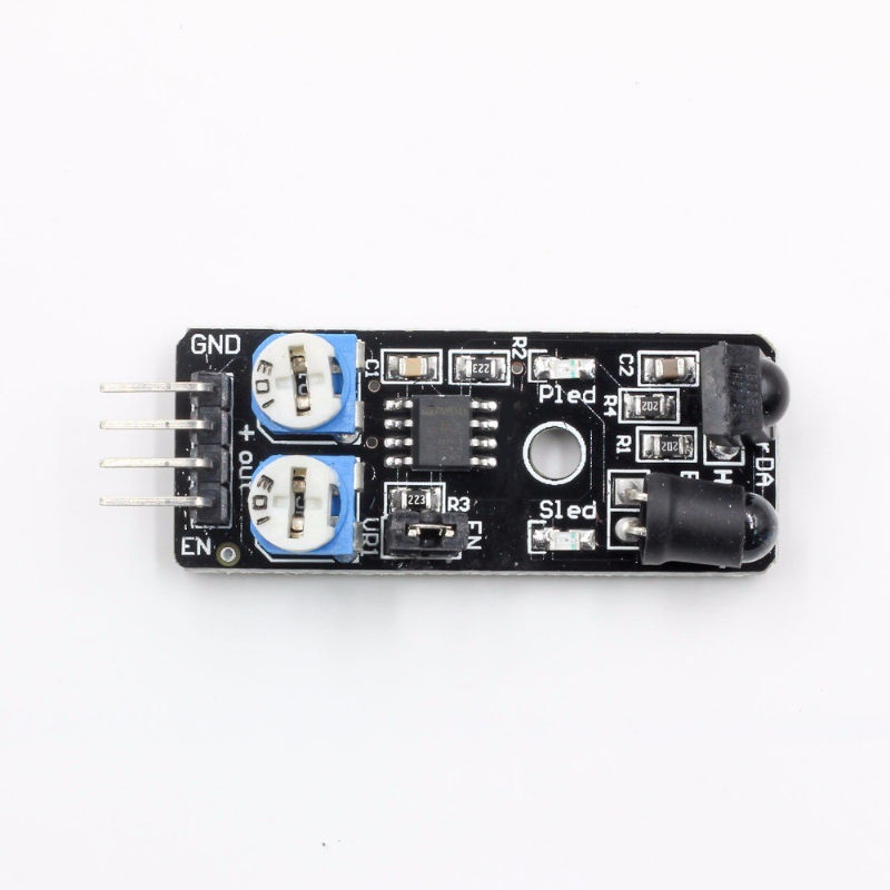
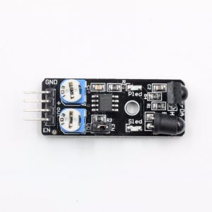
The board includes two indicator LEDs. The PLED is illuminated when the board receives power. The SLED is illuminated momentarily when an obstacle is detected.
Module Adjustments
The module includes a 555 timer that is used to drive the IR LED. There are two single-turn potentiometers for adjusting the frequency and duty cycle of the 555 timer.
Frequency Adjust
The module operates at 38 kHz as the HS0038B receiver module is designed to specifically look for IR pulsing at a 38 kHz rate. The potentiometer next to the GND pin is used to adjust the frequency of the 555 timer and is set to approximately 38 kHz from the factory and shouldn’t be readjusted unless you have a scope or frequency counter to calibrate the frequency.
Duty Cycle Adjust
The other potentiometer allows for adjustment of the duty cycle of the 555 timer. This affects the brightness of the IR LED and it can be fiddled with to try to change the distance at which objects are detected.
If this potentiometer is adjusted too far CW, the module may show that it is always detecting an obstacle even when it isn’t. In this case, adjust the potentiometer CCW until the LED goes off when there is no obstacle in front of the sensor.
Continuous / Pulse Mode Jumper
There is a jumper on the assembly that when installed causes the 555 timer to operate continuously. This mode is most useful for basic testing of the module without requiring it to be hooked to a MCU.
If the jumper is removed, the EN pin on the 4-pin header is then used to enable the 555 timer to operate. This is the more typical way to use this module if using it in an actual application. The reason is the HS0038B receiver module is designed to filter out any IR signals that it sees continually, so it is better to pulse the IR.
Module Connections
There is a 4-pin header on the assembly for making connections.
1×4 Header
- GND = Ground. Must be common with the MCU ground.
- + = Power (3.3 – 5V)
- OUT = Output, normally HIGH. Output is pulsed LOW when an obstacle is detected.
- EN = Enable, active HIGH. When the on-board jumper is installed, EN is pulled to Vcc and always enabled. If jumper is removed, an output pin from a MCU can be used to enable the device.