Product Overview
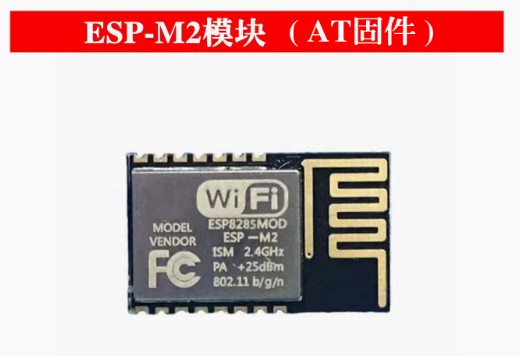
The ESP-M2 WiFi Serial Transparent Transmission Module is a compact, high-performance wireless communication solution designed to bridge the gap between serial devices and Wi-Fi networks. Built around the powerful ESP8285 chip—an enhanced version of the legendary ESP8266 with integrated flash memory—this module provides a seamless “plug-and-play” solution for adding wireless connectivity to your existing projects .
Unlike modules that require complex programming, the ESP-M2 comes preloaded with industrial-grade AT command firmware that allows you to control all Wi-Fi functions using simple serial commands . This makes it incredibly easy to integrate into any microcontroller or computer system: just send AT commands over UART, and the module handles everything from connecting to Wi-Fi networks to sending and receiving data over TCP/IP .
Whether you need to retrofit legacy industrial equipment with wireless monitoring, build a wireless data logger, create a remote control system, or add cloud connectivity to your next IoT project, the ESP-M2 provides a reliable, cost-effective solution. Its compact form factor (34mm × 17mm), integrated PCB antenna, and wide operating voltage range (4.5V-6.0V) make it ideal for both prototyping and production use.
Key Features
-
ESP8285 Core with Integrated Flash: Powered by the ESP8285 chip featuring 1 MB of integrated flash memory, eliminating the need for external flash and improving reliability .
-
Preloaded AT Command Firmware: Comes with industrial-grade AT firmware (compatible with ESP8266 AT command set), allowing complete Wi-Fi control via simple serial commands—no programming required .
-
Complete Wi-Fi Solution: Supports 802.11 b/g/n protocols at 2.4 GHz with integrated PCB antenna. Delivers up to 15dBm output power with excellent receiver sensitivity down to -96dBm .
-
Transparent Transmission Mode: Once configured, the module can operate in transparent transmission mode, automatically forwarding any data received over the serial port to a network connection (TCP/UDP) and vice versa .
-
Built-in Web Configuration Server: Features an onboard HTTP web server that allows you to configure module parameters through a simple web browser—no additional software or apps required .
-
Multiple Operating Modes: Supports Station (STA), Access Point (AP), and Station+AP modes, enabling devices to connect to existing networks or create their own .
-
Rich Network Protocols: Supports TCP Server, TCP Client, UDP Server, UDP Client, and HTTP Client modes, with support for DNS and remote server connections .
-
Ultra-Low Power Consumption: Features multiple sleep modes with deep sleep current as low as 20 µA, making it suitable for battery-powered applications .
-
Wide Operating Voltage: Accepts supply voltage from 4.5V to 6.0V (5V recommended), with TTL logic levels compatible with both 3.3V and 5V systems .
-
Industrial Temperature Range: Rated for operation from -40°C to +125°C, making it suitable for demanding industrial environments and outdoor installations .
-
Status Indicator Output: Provides a dedicated STATE pin (GPIO4) that outputs a low signal when the module is successfully connected to a Wi-Fi network .
-
OTA Firmware Updates: Supports Over-The-Air (OTA) firmware updates for future upgrades .
Technical Specifications
Pinout & Interface Guide
The ESP-M2 module is mounted on a convenient carrier board that provides easy access to all essential pins.
Boot Mode Configuration
The module’s boot mode is determined by the state of GPIO0 :
Status LED Indicator
The onboard LED provides visual feedback of the module’s Wi-Fi connection status :
AT Command Reference
The ESP-M2 uses the standard ESP8266 AT command set. All commands end with a new-line (CR-LF) . The default baud rate is 115200.
Basic AT Commands
Wi-Fi Configuration Commands
TCP/IP Commands
Transparent Transmission Mode
To enter transparent transmission mode:
-
Set AT+CIPMODE=1 (enable transparent mode)
-
Establish a connection with AT+CIPSTART
-
Send AT+CIPSEND to enter transparent mode
-
Any data sent to the serial port will be transmitted directly to the remote server
-
Exit transparent mode by sending +++ (no new-line)
Usage Guide
Getting Started
-
Power the Module: Connect a 5V DC power supply to the VCC and GND pins. The onboard LED should illuminate.
-
Connect to Your Host Device: Connect the module’s TXD pin to the RX pin of your device, and RXD to the TX pin. If your device uses 5V logic, the module’s 3.3V TTL pins are 5V tolerant due to built-in series resistors .
-
Open a Serial Terminal: Use a serial terminal program (such as PuTTY, Arduino Serial Monitor, or minicom) set to 115200 baud, 8 data bits, 1 stop bit, no parity.
-
Test Communication: Send the AT command. The module should respond with OK.
Basic Configuration Example
// Test communication
AT
OK

// Check firmware version
AT+GMR
AT version:1.7.4.0(May 11 2020 19:13:04)
SDK version:3.0.4
compile time:Jun 18 2020 09:33:58
OK

// Set to Station mode
AT+CWMODE=1
OK

// Connect to Wi-Fi network
AT+CWJAP="MyWiFi","password123"
WIFI CONNECTED
WIFI GOT IP
OK

// Get IP address
AT+CIFSR
+CIFSR:STAIP,"192.168.1.100"
+CIFSR:STAMAC,"84:0d:8e:xx:xx:xx"
OK
TCP Client Example
// Set single connection mode
AT+CIPMUX=0
OK

// Connect to a TCP server (IP address 192.168.1.200, port 8080)
AT+CIPSTART="TCP","192.168.1.200",8080
CONNECT
OK

// Send 5 bytes of data
AT+CIPSEND=5
> HELLO
Recv 5 bytes
SEND OK

// Close connection
AT+CIPCLOSE
OK
TCP Server Example
// Set multiple connection mode (required for server)
AT+CIPMUX=1
OK

// Start TCP server on port 8080
AT+CIPSERVER=1,8080
OK

// Check for client connection
AT+CIPSTATUS
STATUS:2
+CIPSTATUS:0,"TCP","192.168.1.101",49152,8080,0
OK
Connection Diagrams
Basic Connection to a Microcontroller:
ESP-M2 Module          Microcontroller (Arduino/STM32/etc.)
   TXD      ----->           RXD
   RXD      <-----           TXD
   GND      ----->           GND
   VCC      ----->           5V (external supply)
Connection to a Computer for Testing:
ESP-M2 Module          USB-to-TTL Adapter
   TXD      ----->           RX
   RXD      <-----           TX
   GND      ----->           GND
   VCC      ----->           5V (from adapter or external)
Q: What is the difference between ESP-M2 and ESP-01?
The ESP-M2 offers several advantages:
-
Integrated flash: 1MB built-in flash (no external flash chip)
-
Built-in carrier board: Includes voltage regulator, power filtering, and convenient pin headers
-
5V tolerant inputs: Direct connection to 5V microcontrollers without level shifters
-
Wider operating voltage: 4.5V-6.0V (vs 3.3V only on ESP-01)
Q: Do I need to write code to use this module?
No. The module comes preloaded with AT firmware. You can control it entirely using simple serial commands from any microcontroller or computer. The AT command set is well-documented and easy to use .
Q: What is transparent transmission mode?
Transparent transmission mode is a special mode where the module automatically forwards any data received on the serial port directly to a pre-established network connection (TCP or UDP). This is ideal for applications where you want a simple “wire replacement” for serial cables .
Q: What types of devices can I connect to the ESP-M2?
The module connects via standard UART (serial) interface. It can interface with:
-
Microcontrollers (Arduino, STM32, ESP32, etc.)
-
Industrial PLCs and controllers
-
Single-board computers (Raspberry Pi, etc.)
-
Any device with a TTL serial port
Q: Can I use the ESP-M2 with 5V logic devices?
Yes. The module’s TXD and RXD pins have built-in series resistors and are 5V tolerant, allowing direct connection to 5V logic devices without level shifters .
Q: What voltage does the ESP-M2 require?
The module requires a supply voltage of 4.5V to 6.0V DC, with 5V recommended. Do not apply 3.3V directly to the VCC pin—the module has an onboard regulator that requires at least 4.5V to function properly .
Q: How much current does the ESP-M2 draw?
Current consumption varies by operating mode:
Q: Can I power the ESP-M2 with batteries?
Yes. The module’s deep sleep current of 20µA makes it suitable for battery-powered applications. A 5V boost converter or a 4.5-6.0V battery pack is required.
Q: How do I connect the module to my device?
Connect the module’s TXD to your device’s RX, RXD to your device’s TX, and GND to GND. Power the module with a separate 5V supply. No additional resistors or level shifters are needed for 5V logic devices .
Q: How do I access the web configuration page?
By default, the module may boot in AP mode with a default SSID (check the label on your module). Connect to this network, then open a web browser and navigate to 192.168.4.1 .
Q: What is the default baud rate?
The default baud rate is 115200 bps, 8 data bits, 1 stop bit, no parity.
Q: How do I reset the module to factory defaults?
Send the command AT+RESTORE. The module will restore all settings to factory defaults and restart .
Q: The module is not connecting to my Wi-Fi network. What should I check?
Verify the following:
-
Your Wi-Fi network operates on 2.4 GHz (5 GHz is not supported)
-
The SSID and password are entered correctly (case-sensitive)
-
Your router is not blocking new devices
-
Check the STATUS LED—if it’s blinking slowly, the module is not connected
Q: What does the STATE pin do?
The STATE pin (GPIO4) outputs a LOW signal when the module is successfully connected to a Wi-Fi network. This can be used to drive an LED or signal to your host device.
Q: How do I exit transparent transmission mode?
Send the characters +++ with no new-line (CR-LF). Do not send any other characters for at least 1 second before and after the +++ sequence .
Q: What can I build with the ESP-M2?
Popular applications include :
-
Wireless data acquisition: Replace cables with wireless links for sensors and instruments
-
Industrial equipment retrofitting: Add Wi-Fi monitoring to legacy machinery
-
Smart home devices: Wireless control of lights, appliances, and HVAC
-
Robot control: Remote control via Wi-Fi for robotic platforms
-
Wireless serial printers: Eliminate cables for point-of-sale or industrial printers
-
Remote sensor networks: Deploy battery-powered sensors with data logging
Q: Is the ESP-M2 suitable for industrial applications?
Yes. The module is rated for operation from -40°C to +125°C, making it suitable for demanding industrial environments and outdoor installations .
Q: Can I update the firmware over-the-air?
Yes. The module supports OTA (Over-The-Air) firmware updates, allowing you to upgrade the firmware wirelessly without physical access .
Q: Can I reprogram the module with custom firmware?
Yes. The ESP8285 is fully compatible with the ESP8266 ecosystem. You can reprogram the module using the Arduino IDE, ESP-IDF, or other development tools by putting it into programming mode (pulling GPIO0 LOW during boot) .