2-Bit MAX7219 dot matrix module 8*16 single-chip microcomputer control drive LED display module RED 1088AS Common Cathode

SKU: FA2092-0
Operating Voltage

5V DC (4.0V – 5.5V)

Operating Current

30mA – 80mA (typical) / 320mA (max, all LEDs on)

Shutdown Mode Current

150 µA

Display Resolution

8 × 16 pixels (two 8×8 matrices side by side)

Total LEDs

128 red LEDs

LED Matrix Type

1088AS Common Cathode

Driver IC

MAX7219 (serial input/output common-cathode driver)

Communication Protocol

SPI (Serial Peripheral Interface)

I/O Pin Requirements

3 pins (DIN, CS, CLK) + VCC, GND

Description

The 2-Bit MAX7219 Dot Matrix Module is a compact and efficient LED display solution that combines two 8×8 dot matrix units into a single 8×16 pixel display panel. This module is specifically designed for single-chip microcomputer (MCU) control applications, offering a convenient way to add visual output to your embedded projects without complex wiring or multiplexing code.

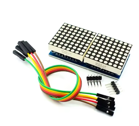
The module features two 1088AS common cathode red LED matrices, arranged side by side to create a display area of 8 rows by 16 columns (128 individual red LEDs). Each of the 128 LEDs can be independently controlled, enabling the display of custom characters, scrolling text, simple graphics, animations, and status indicators.

At the heart of this module is the MAX7219 integrated circuit driver, a specialized serial input/output common-cathode display driver that dramatically simplifies the process of controlling LED matrices. The MAX7219 handles all the complex multiplexing and refresh timing internally, eliminating the need for constant microcontroller intervention and ensuring flicker-free display performance. The driver includes an 8×8 static RAM for storing display data, a BCD decoder, a multiplex scan circuit, and segment drivers—all integrated into a single chip.

The module communicates via a simple 3-wire or 4-wire SPI interface (VCC, GND, DIN, CS, CLK), requiring only three I/O pins from your microcontroller to control all 128 LEDs. This efficient communication protocol allows the module to be easily integrated with popular development platforms including Arduino, ESP32, ESP8266, STM32, 8051, AVR, PIC, and other SPI-compatible microcontrollers.

Key design benefits include:

  • Flicker-free operation – The MAX7219 automatically refreshes the display at approximately 800 Hz

  • Software-controlled brightness – 16 discrete brightness levels from 0 to 15

  • Low microcontroller overhead – SPI communication minimizes CPU usage

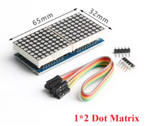
  • 2-in-1 compact design – Two 8×8 modules pre-assembled for 8×16 resolution

  • Low power consumption – Shutdown mode consumes only 150µA

The module uses 1088AS common cathode red LEDs, providing bright, high-contrast red illumination that is clearly visible in both indoor and well-lit environments. The PCB features mounting holes for secure installation and standard 2.54mm pin headers for easy connection to your development board.

Whether you need to build a small scrolling message display, a real-time sensor readout, a simple game interface, or a status indicator for your MCU project, this 2-bit MAX7219 dot matrix module delivers reliable, easy-to-control LED display capability in a compact form factor.

Key Features

  • 2-in-1 Integrated Design – Two 8×8 dot matrix modules pre-assembled into a single 8×16 pixel display panel (128 total LEDs)

  • MAX7219 Driver Chip – Handles all multiplexing and refresh timing automatically for flicker-free display

  • 1088AS Common Cathode LED Matrices – Bright red LEDs with excellent visibility and contrast

  • Simple SPI Interface – Only 3 I/O pins required to control all 128 LEDs (DIN, CS, CLK)

  • Software Brightness Control – 16 adjustable brightness levels via register setting (0x0 to 0xF)

  • 5V Operating Voltage – Compatible with 5V microcontrollers; 3.3V logic devices may require level shifting

  • Individual LED Control – Each of the 128 LEDs can be addressed independently

  • Low Power Shutdown Mode – Consumes only 150µA in power-down mode

  • Compact Form Factor – Saves space compared to using two separate 8×8 modules

  • Library Support – Extensive community libraries available (LedControl, MD_Parola, MD_MAX72XX, MaxMatrix)

Technical Parameters

Parameter Value
Operating Voltage 5V DC (4.0V – 5.5V)
Operating Current 30mA – 80mA (typical) / 320mA (max, all LEDs on)
Shutdown Mode Current 150 µA
Display Resolution 8 × 16 pixels (two 8×8 matrices side by side)
Total LEDs 128 red LEDs
LED Matrix Type 1088AS Common Cathode
Driver IC MAX7219 (serial input/output common-cathode driver)
Communication Protocol SPI (Serial Peripheral Interface)
I/O Pin Requirements 3 pins (DIN, CS, CLK) + VCC, GND

Usage Guide

Hardware Overview

The module consists of two 1088AS 8×8 red LED matrix panels arranged side by side, driven by a single MAX7219 IC (or dual ICs depending on the specific board design). The module features input and output headers allowing multiple units to be cascaded for larger displays.

Component Identification:

  • LED Panels: Two 1088AS 8×8 red LED matrices (8 rows × 16 columns total)

  • MAX7219 IC: Driver chip (handles multiplexing and refresh)

  • Input Header (5 pins) : Connects to your microcontroller

  • Output Header (5 pins) : For cascading to additional modules

1088AS Common Cathode Information

The 1088AS is a standard 8×8 common cathode red LED matrix. In a common cathode configuration, all LEDs in the same row share a common cathode (negative) connection, while columns provide the anode (positive) connections. This configuration is specifically designed for use with the MAX7219 driver IC. The MAX7219 works by sourcing current to 8 anodes (columns) and sinking current from one common cathode (row) at a time, scanning across all rows at approximately 800 Hz to create a flicker-free image.

Pinout Description

The module uses a standard 5-pin header (2.54mm pitch) for connections:

Pin Label Function Connection
VCC Power Supply Connect to 5V (do not exceed 5.5V)
GND Ground Connect to common ground with microcontroller
DIN Data Input Connect to microcontroller MOSI/SPI Data pin
CS Chip Select Connect to any digital I/O pin (library configurable)
CLK Clock Connect to microcontroller SPI Clock pin

Wiring Instructions

Step 1 – Connect to Microcontroller

Arduino Uno/Nano Connection:

Module Pin Arduino Pin
VCC 5V
GND GND
DIN Pin 11 (MOSI)
CS Pin 10 (configurable)
CLK Pin 13 (SCK)

ESP32 Connection:

Module Pin ESP32 Pin
VCC 5V (external power recommended for multiple modules)
GND GND
DIN GPIO23 (MOSI)
CS GPIO5 (configurable)
CLK GPIO18 (SCK)

ESP8266 Connection:

Module Pin ESP8266 Pin
VCC 5V (external power recommended)
GND GND
DIN GPIO13 (MOSI – HSPI)
CS GPIO15 (configurable)
CLK GPIO14 (SCK – HSPI)

Raspberry Pi Connection:

Module Pin Raspberry Pi GPIO (BCM)
VCC 5V Pin
GND GND Pin
DIN GPIO10 (MOSI)
CS GPIO8 (CE0)
CLK GPIO11 (SCLK)

⚠️ Important: For Raspberry Pi and other 3.3V logic devices, the MAX7219 requires 5V power, but the logic signals (DIN, CS, CLK) should ideally be level-shifted from 3.3V to 5V for reliable operation. While some users report success without level shifting, voltage level converters are recommended for production installations.

Step 2 – Power Considerations

  • A single 2-bit (8×16) module draws approximately 30-80mA under normal operation

  • Maximum current can reach 320mA when all 128 LEDs are illuminated at full brightness

  • Most microcontroller 5V pins can supply 400-500mA, sufficient for one module

  • For cascaded modules or high-brightness applications, use an external 5V power supply

  • Adding a filter capacitor (1µF or larger) across VCC and GND near the module can improve stability

Cascading Multiple Modules

To create larger displays, connect additional modules in a daisy chain:

  1. Connect the output header of the first module to the input header of the second module

  2. Match pins: VCC→VCC, GND→GND, DIN→DOUT, CS→CS, CLK→CLK

  3. Update the MAX_DEVICES parameter in your code to match the total number of 8×8 units (each 2-bit module counts as 2 devices)

Cascading Example:

  • 1 module (2-bit) = 8×16 pixels (2 devices)

  • 2 modules = 8×32 pixels (4 devices)

  • 4 modules = 8×64 pixels (8 devices)

Software Setup

Arduino – LedControl Library

  1. Install Library: Open Arduino IDE → Tools → Manage Libraries → Search “LedControl” → Install

  2. Basic Initialization Code (for 2-bit module as 2 devices) :

cpp
#include "LedControl.h"

// Pin connections: DIN, CLK, CS, number of 8x8 devices (2 for this module)
// This module has 2 matrices = 2 devices
LedControl lc = LedControl(11, 13, 10, 2);

void setup() {
  // Initialize both 8x8 matrices
  for (int device = 0; device < 2; device++) {
    lc.shutdown(device, false);    // Wake up from power-saving mode
    lc.setIntensity(device, 8);    // Set brightness (0=min, 15=max)
    lc.clearDisplay(device);       // Clear the display
  }
}

void loop() {
  // Light a single LED on the first matrix (device 0, row 0, col 0)
  lc.setLed(0, 0, 0, true);
  delay(500);
  lc.setLed(0, 0, 0, false);
  delay(500);
  
  // Light a single LED on the second matrix (device 1, row 0, col 0)
  lc.setLed(1, 0, 0, true);
  delay(500);
  lc.setLed(1, 0, 0, false);
  delay(500);
}

Arduino – MD_Parola Library (Scrolling Text Across 8×16 Display)

For advanced scrolling text effects, install both MD_Parola and MD_MAX72XX libraries:

cpp
#include <MD_Parola.h>
#include <MD_MAX72xx.h>
#include <SPI.h>

// Hardware type – try FC16_HW first for common cathode modules
#define HARDWARE_TYPE MD_MAX72XX::FC16_HW
#define CS_PIN 10
#define MAX_DEVICES 2  // Two 8x8 devices = 8x16 total

MD_Parola display = MD_Parola(HARDWARE_TYPE, CS_PIN, MAX_DEVICES);

void setup() {
  display.begin();
  display.setIntensity(8);   // Brightness 0-15
  display.displayClear();
}

void loop() {
  display.displayScroll("Hello!", PA_CENTER, PA_SCROLL_LEFT, 100);
  while (!display.displayAnimate()) { /* wait */ }
  delay(1000);
}

Important Note on Hardware Type: If the displayed text appears reversed or upside down, change the HARDWARE_TYPE definition:

  • #define HARDWARE_TYPE MD_MAX72XX::FC16_HW (most common)

  • #define HARDWARE_TYPE MD_MAX72XX::PAROLA_HW

  • #define HARDWARE_TYPE MD_MAX72XX::GENERIC_HW

Display Patterns on 8×16 Layout

The 8×16 display is organized as two adjacent 8×8 matrices. Device 0 controls the left matrix (columns 0-7), and Device 1 controls the right matrix (columns 8-15).

To display a pattern across the full 8×16 display:

cpp
// Define patterns for left and right halves
byte leftPattern[8] = {
  B00111100,
  B01000010,
  B10100101,
  B10000001,
  B10100101,
  B10011001,
  B01000010,
  B00111100
};

byte rightPattern[8] = {
  B00111100,
  B01000010,
  B10011001,
  B10100101,
  B10000001,
  B10100101,
  B01000010,
  B00111100
};

// Display on both matrices
for (int row = 0; row < 8; row++) {
  lc.setRow(0, row, leftPattern[row]);   // Left matrix (device 0)
  lc.setRow(1, row, rightPattern[row]);  // Right matrix (device 1)
}

8051/AVR/PIC Single-Chip Microcomputer Integration

For traditional MCUs like 8051, AVR (non-Arduino), or PIC, you can drive the MAX7219 using bit-banged SPI or hardware SPI. The key steps are:

  1. Set up three I/O pins for DIN, CLK, and CS

  2. Send 16-bit commands (register address in high byte, data in low byte)

  3. Pulse the CLK pin for each bit (MSB first)

  4. Toggle CS/LOAD to latch the data

Basic bit-bang sequence for any MCU:

  • Set CS low

  • For each of 16 bits (MSB to LSB):

    • Set DIN to bit value

    • Pulse CLK high then low

  • Set CS high to latch data

Installation Tips

  • Mounting: Secure using mounting holes with M3 screws or double-sided tape

  • Ventilation: Ensure adequate airflow around the module, especially in cascaded configurations

  • Cable Length: Keep SPI wires as short as possible (under 50cm) to prevent signal degradation

  • Level Shifting: For 3.3V microcontrollers, use a 4-channel bi-directional logic level converter

  • Filter Capacitors: Adding a 1µF or larger capacitor across VCC and GND near each module improves stability

  • Enclosure: For outdoor installations, protect the module in a weatherproof enclosure

Q: What does "2-Bit" mean in this product name?

“2-Bit” refers to the fact that this module contains two 8×8 dot matrix units, creating a combined display of 8×16 pixels. The term “bit” in this context refers to each individual 8×8 matrix module

Q: What is the difference between common cathode and common anode?
Feature Common Cathode (This Module) Common Anode
Row/Column Wiring Cathodes (negative) are common per row Anodes (positive) are common per row
MAX7219 Compatibility Directly compatible Requires additional components
Current Flow Sinks current through cathodes Sources current through anodes

The 1088AS common cathode matrix is specifically designed to work directly with the MAX7219 driver without additional circuitry

Q: Can I use this module with 3.3V microcontrollers like ESP32 or Raspberry Pi?

The MAX7219 requires 5V power for reliable operation. For 3.3V logic devices:

  • Power: Connect VCC to 5V (from external supply or 5V pin)

  • Signals: Use a logic level converter for DIN, CS, and CLK pins

  • The ESP32 has 5V-tolerant pins, but level shifters are still recommended for production use

Q: What library should I use for Arduino?

Three popular libraries are:

  • LedControl: Simple, good for basic patterns and custom animations

  • MD_Parola (with MD_MAX72XX): Advanced scrolling text effects, multiple fonts, and alignment options

  • MaxMatrix: Good for basic matrix control

Q: Why is my text displayed backwards or upside down?

This is a common issue caused by incorrect hardware type definition. Try changing the HARDWARE_TYPE in your code:

cpp
#define HARDWARE_TYPE MD_MAX72XX::FC16_HW    // Most common
#define HARDWARE_TYPE MD_MAX72XX::PAROLA_HW
#define HARDWARE_TYPE MD_MAX72XX::GENERIC_HW
Q: Can I cascade multiple 2-bit modules together?

Yes. Connect the output header of one module to the input header of the next. Each 2-bit module contains two 8×8 matrices, so update the MAX_DEVICES parameter to 2 × number_of_modules (e.g., 2 modules = 4 devices).

Q: How do I control the brightness?

Brightness can be adjusted in software using:

  • LedControllc.setIntensity(device, value) where value = 0 (min) to 15 (max)

  • MD_Paroladisplay.setIntensity(value)

The MAX7219 supports 16 discrete brightness levels

Q: What is the maximum current draw?
  • Normal operation: approximately 30-80mA

  • All 128 LEDs at maximum brightness: up to 320mA

  • For cascaded modules, total current adds: 2 modules could draw over 640mA at full brightness

  • For multiple modules, use an external 5V power supply

Q: Can I use this module for both home and business applications?

Home users: Small message boards, IoT status displays, clock projects, home automation status indicators, simple games.

Business users: Small retail signage, industrial equipment status displays, queue management displays, laboratory equipment readouts, small public information displays.

Q: Does the module remember the display content after power loss?

No. The MAX7219 has volatile memory. When power is lost, the display content is cleared. Your microcontroller must re-send display data during startup